
Quick Answer
Inductance is the property that makes a circuit oppose any change in its current, by generating a voltage that resists the change. Its SI unit is the henry, one volt-second per ampere. Any current-carrying conductor has some; a coil concentrates it, and a magnetic core multiplies it.
Intuition
Electrical flywheel
A flywheel is a heavy disc on a shaft, and it has one memorable habit: it hates being told to change speed. Start it from rest and it resists, absorbing effort for a long while before it is really turning. Try to stop it and it resists again, shoving back at whatever is trying to slow it down. Once it is spinning steadily it takes almost nothing to keep it there.
Inductance is that habit, in a circuit. An inductor does not oppose current — a steady current passes through a coil almost as freely as through a straight wire. What it opposes is change in the current. Speed the current up and the coil pushes back against the increase. Slow it down and the coil pushes the other way, trying to keep the current going.
The mechanism is magnetic. Current through a wire makes a magnetic field around it, and winding the wire into a coil stacks those fields on top of each other into something much stronger. When the current changes, that field has to change with it, and a changing magnetic field through a loop of wire generates a voltage in that loop. The voltage always appears in the direction that fights the change, which is why the flywheel comparison holds so well.
The unit is the henry, after Joseph Henry, and it is defined by that opposition: a coil of one henry produces one volt when its current changes at one ampere per second. The henry is a large unit for electronics work, so ordinary parts are marked in millihenries, microhenries and sometimes nanohenries — but unlike the farad, whole henries do turn up, in mains transformers and audio chokes.
Practitioner
The voltage a coil produces when you change its current
The definition converts straight into the number a designer actually wants: how much voltage appears when the current moves. Over a finite interval:
Worked example — Switching a relay coil, slowly and then quickly
A coil of 10 mH is carrying 2.0 A and the current is brought to zero.
Do it gently, over 1.0 ms, and the coil generates 20 V across itself.
Do it with a switch or a transistor, so the current collapses in 1.0 µs instead, and the same equation asks for 20 kV.
That second figure is what the equation demands, not what a bench measurement would show. In a real circuit the voltage climbs until something gives way first: an arc jumps the switch contacts, or a semiconductor breaks down, or a snubber or flyback diode offers the current a path and pins the voltage to something survivable. Every one of those outcomes is the circuit refusing to let the current change as fast as the switch tried to make it.
Working with inductors therefore starts with a habit: never interrupt current in an inductive load without giving it somewhere to go. Relay coils, solenoids, motors and transformer windings all need a diode, a snubber or a clamp across them, fitted as part of the design rather than added after the first failure.
Current through an inductor cannot change instantly either, because that would need infinite voltage — so an inductor at the instant of switching behaves as though it were still carrying whatever current it had a moment before. At a steady current, meanwhile, the voltage across an ideal inductor is zero, so once a DC circuit has settled the coil looks like a plain piece of wire, with only its winding resistance left.
Inductance is not confined to components called inductors. Every wire, every PCB track, every component lead has some, roughly a nanohenry per millimetre of length for ordinary wiring. That is negligible at audio frequencies and decisive at switching speeds, which is why supply decoupling is placed at the chip rather than at the connector, and why a long ground lead ruins a fast measurement.
Engineer
Turns, area and core material, and why the turns count squares
Inductance is set by geometry and by the magnetic material inside the winding, the same way capacitance is set by geometry and the dielectric. For a single-layer coil that is long compared with its diameter, the field inside is nearly uniform and the result is simple:
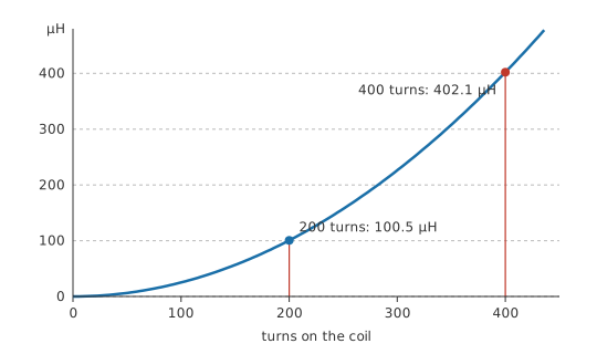
The turns count appears squared, and it is worth understanding why. Doubling the turns doubles the magnetic field the coil produces for a given current, and doubles the number of turns that field then passes through. Both effects multiply, so the inductance goes up fourfold.
Worked example — A coil, then twice the turns, then a core
Wind 200 turns over a length of 0.05 m with a cross-section of 0.0001 m², in air, where the relative permeability is 1.0. With μ₀ at 1.2566 µH/m, the coil comes to 100.5 µH.
Double the winding to 400 turns on the same former and it becomes 402.1 µH — four times as much, from twice the wire.
Now leave the turns at 200 and slide in a core of relative permeability 800. The same coil becomes 80.4 mH.
The core is doing what a dielectric does for a capacitor, and for a related reason: the material's own magnetic domains line up with the applied field and reinforce it. The gain is far larger than any dielectric offers, and it comes with a far worse set of side effects.
Chief among them is saturation. A dielectric's permittivity sags gradually under field; a core's permeability collapses. Once every domain in the material is aligned, no further alignment is available, and the core contributes nothing beyond that point — the coil's inductance falls abruptly towards its air-cored value. In a switching circuit that shows up as current that was rising in a straight line suddenly shooting upwards, and it destroys switching transistors regularly. Saturation is set by the flux in the core, so it depends on current, turns and core cross-section, and it is a hard limit rather than a gentle derating.
The model has other limits worth naming. The formula assumes a long coil, and a short fat one has significantly less inductance than it predicts, because the field spreads out at the ends. It assumes a constant permeability, whereas real ferromagnetic materials have permeability that varies with flux, with frequency and with temperature, and that traces a hysteresis loop rather than a line. And it assumes all the flux links all the turns, which is only ever approximately true — the shortfall is exactly what mutual inductance has to account for when two windings share a core.
Professional
Choosing a real inductor
The inductance value is often the least interesting number in an inductor's datasheet.
Worked example — The resistance that comes free with every winding
An inductor wound to give some particular value has 80 mΩ of winding resistance and carries 2.0 A of DC.
Its winding therefore dissipates 320 mW before any switching loss is counted. In a small surface-mount part that is enough to warm it noticeably.
Winding resistance and inductance pull against each other, because more turns buys inductance as the square and costs resistance in direct proportion, while thicker wire cuts the resistance and takes up room that would otherwise hold turns. Every inductor is a settlement between those two, made in a fixed volume.
Current ratings come in two flavours and they mean different things. The saturation current is where the core gives up and the inductance falls away, usually quoted at a stated percentage drop. The RMS or heating current is where the winding losses raise the part's temperature to its limit. Whichever is lower governs, and which one that is depends on the part — using an inductor beyond its saturation rating is an instantaneous circuit failure, while exceeding its thermal rating is a slow reliability problem.
Above a certain frequency an inductor stops being one. Every winding has capacitance between its turns, and that turn-to-turn capacitance resonates with the inductance at the part's self-resonant frequency. Below it the part is inductive; above it, capacitive. A choke chosen to block a frequency it happens to sit above is worse than no choke at all, which is why a datasheet's impedance curve is the plot to read rather than the inductance figure.
Core material sets the rest of the character. Ferrite is cheap and has high permeability but saturates sharply and has significant loss at high flux; powdered-iron and alloy-powder cores saturate gently, in a soft roll-off that is much friendlier to a switching regulator; air cores never saturate at all and are what high-frequency work uses when linearity matters more than size. Core loss rises steeply with both frequency and flux swing, and it is the term that decides how hot a switching inductor runs. The inductor component and ferrite bead lessons take the families apart.
Parasitic inductance deserves the same design attention as the deliberate kind. A capacitor's leads, a PCB via, a connector pin, a ground plane slot — each adds nanohenries, and at fast edges those nanohenries generate real volts. The whole discipline of high-speed layout is largely about keeping the current loops small so that this unavoidable inductance stays small too.
Safety
The kilovolt figure in Layer 2 is arithmetic on paper, not a measurement anyone should go looking for. It is worth respecting anyway: the same effect is what an ignition coil is built to exploit, and an inductive load switched carelessly can produce a genuine shock hazard and destroy semiconductors nearby. Treat any coil that has been carrying current as a live part until it has been given a discharge path, and fit the clamp diode or snubber before the first power-up rather than after the first failure. Mains-connected windings — transformer primaries, motor windings, contactor coils — are covered by electrical safety fundamentals and are not bench work for the unsupervised.
Common mistakes
- Thinking an inductor opposes current — it opposes a change in current. A settled DC circuit sees little more than the winding resistance.
- Switching an inductive load with no clamp — the collapsing current generates whatever voltage it takes to keep flowing, and something in the circuit will break down to provide it.
- Reading only the inductance figure on a datasheet — saturation current, winding resistance and self-resonant frequency decide whether the part works in your circuit.
- Assuming a coil is inductive at every frequency — above its self-resonant frequency, turn-to-turn capacitance dominates and the part behaves as a capacitor.
- Adding turns to get more inductance without checking saturation — more turns raise the flux for the same current and bring the saturation limit closer.
- Ignoring the inductance of ordinary wiring — a nanohenry per millimetre is nothing at audio frequencies and a great deal at nanosecond edges.
Frequently asked questions
What is inductance?
The property that makes a circuit oppose any change in its current, by producing a voltage that resists the change. It is measured in henries: one henry produces one volt when the current through it changes at one ampere per second.
Why does an inductor produce a voltage spike when switched off?
The voltage a coil generates is proportional to how fast its current is changing. A switch tries to take the current to zero almost instantly, so the demanded voltage is enormous, and it rises until an arc, a breakdown or a clamp diode gives the current somewhere to go.
What does a magnetic core do?
Its domains align with the coil's field and reinforce it, multiplying the inductance by the material's relative permeability — often by hundreds or thousands. The price is saturation, core loss, and a permeability that varies with flux, frequency and temperature.
Why does doubling the turns quadruple the inductance?
More turns make a stronger field for a given current, and there are also more turns for that field to link. The two effects multiply, so inductance follows the square of the turn count.
Does a straight wire have inductance?
Yes, roughly a nanohenry per millimetre for ordinary wiring. It is irrelevant at audio frequencies and decisive at fast switching edges, which is why decoupling capacitors are placed close to the pins they serve.
Knowledge check
A 100 µH inductor's current changes by 0.5 A in 10 µs. What voltage appears across it? (Show answer)
An air-cored coil is rewound with three times the turns on the same former. What happens to its inductance? (Show answer)
Why must an inductive load never be switched off without a clamp? (Show answer)
An inductor's current rises linearly, then suddenly shoots up. What has happened? (Show answer)
Why is an inductor useless as a choke above its self-resonant frequency? (Show answer)
References
- CODATA / NIST, Fundamental Physical Constants — the magnetic constant μ₀, which since the 2019 revision of the SI is a measured quantity very close to, but no longer exactly, 4π × 10⁻⁷ H/m.