
Quick Answer
Inductive reactance is an inductor's opposition to alternating current, measured in ohms. It equals two pi times the frequency times the inductance, so it rises in direct proportion to frequency: a coil passes direct current freely and obstructs fast signals. Unlike resistance, it dissipates nothing: energy taken in during one part of the cycle comes back in the next.
Intuition
Opposition that grows with speed
A coil pays no attention to a current that is holding steady. It pays a great deal to any attempt to change one. Push the current up and the coil produces a voltage opposing the rise; let it fall and that voltage reverses to hold the current up. Inductance is the name for the habit, and the flywheel it gets compared to catches it: real effort to get one turning, and as much again to stop it.
Alternating current never holds steady at anything. It climbs to a peak, falls back through zero, climbs the other way and starts again, so the coil is asked to change its current for the whole of that journey. Run the alternation faster and every climb is steeper, so the coil pushes back harder. A coil that hardly notices a slow alternation puts up a serious fight against a quick one.
That opposition is measurable, and it comes out in ohms, the same unit as resistance, since it does the same job of setting how much current a given voltage can drive. It carries its own name, inductive reactance, to keep it apart from resistance. A resistor's ohms are the same at every speed; a coil's climb with the speed. A resistor also turns everything it takes into heat, while a coil borrows energy for part of each cycle and hands all of it back during the rest, so reactance on its own warms nothing.
One coil can therefore be barely noticeable to a slow signal and close to an open circuit to a fast one. A component fitted to exploit that is a choke, and it is how an unwanted high frequency is held out of a circuit that still has to pass the wanted low one.
Practitioner
Ohms at a stated frequency
Henries multiplied by hertz give ohms, once the factor of two pi has turned cycles per second into radians per second. Beyond that conversion the relationship says only one thing, and says it strictly: reactance is zero at DC and climbs without limit as the frequency does, along a straight line with no corner and no plateau anywhere in it.
A reactance figure means nothing on its own. The inductance is a property of the part; the reactance is a statement about that part at one frequency and no other, and quoting it without the frequency it was worked out at loses most of the information.
Worked example — One choke, three decades of frequency
A choke of 4.7 mH is fitted in series with a supply line.
At 50 Hz its reactance is 1.48 Ω, comparable with the resistance of the wire it is wound from.
At 1.0 kHz the reactance has risen to 29.5 Ω, and at 100 kHz to 2.95 kΩ.
Three decades of frequency, three decades of reactance.
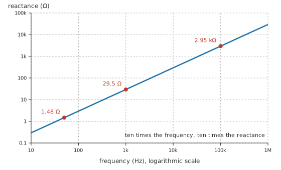
Logarithmic axes turn the proportionality into a straight line, and its slope is worth memorising because it makes estimates cheap: one decade along the frequency axis is one decade up the reactance axis. A single calculated point therefore fixes the whole line, and everything else can be read off in decades without touching a calculator.
For the current a source can push through that reactance, Ohm's law carries over unchanged:
At a single frequency, and for magnitudes alone, reactance sits in the place resistance occupies: the voltage divided by the reactance gives the current. That restriction to magnitudes hides something, and Layer 3 brings it out.
Worked example — What the choke lets through
Put 2.0 V RMS across the same choke at 1.0 kHz and the current settles at 67.7 mA.
Leave the drive alone and move to 100 kHz, and the same coil allows only 0.677 mA.
An LCR meter reports inductance at a test frequency of its own choosing, so a reading taken on the bench is not automatically the value the part will show in a circuit running somewhere else on the axis. The other thing to watch sits at the bottom of that axis: an inductor is a short circuit at DC, with only its winding resistance in the way, so a coil placed across a supply rail with nothing else in the loop will draw whatever the supply can deliver. Reactance protects nothing at zero frequency. Engineering notation keeps the millihenries and the kilohertz honest while the arithmetic is being done.
Engineer
From the rate of change to a number in ohms
An inductor is defined by a rate: the voltage across it equals its inductance multiplied by the rate at which its current is changing. Layer 2 is what that definition returns when a sine wave is fed into it.
Take a current that varies as a sine. Its rate of change is steepest as the current crosses zero and momentarily zero at each peak, and the curve traced out by that rate of change is itself a sine of the same frequency, moved a quarter of a cycle earlier. How large that rate of change gets depends on how quickly the whole pattern is running, and the natural measure of that is angular frequency, in radians per second:
At 1.0 kHz that comes to 6283.2 rad/s.
The voltage across the coil is therefore a wave of the same frequency whose peak is the current's peak multiplied by the angular frequency and by the inductance. Their ratio, of peak to peak or equally of RMS to RMS since both are scaled by the same factor, is the angular frequency times the inductance. Written in hertz instead of radians per second, that is two pi f L, which is the reactance Layer 2 opened with. One assumption carried the derivation: that the current is a sine at a single frequency.
The differentiation also did something the reactance figure fails to record. The current went in as a sine and the voltage came out shifted a quarter of a cycle ahead of it, so the voltage reaches its peak before the current does. One cycle at 1.0 kHz lasts 1.0 ms, which puts the current 250 µs behind the voltage. The standard wording is that current lags voltage by ninety degrees in an inductor, and a capacitor does the reverse, its current arriving early: capacitive reactance is the mirror of this page and phase sets out the vocabulary properly.
That quarter cycle is also why an ideal reactance dissipates nothing. Power is voltage times current instant by instant, and with the two waves in quadrature the product is positive for a quarter of the cycle and negative for the next quarter, in equal measure. Energy goes into the magnetic field and comes back out of it, and the average over a whole cycle is zero.
Because reactance is a ratio of amplitudes, it cannot express that quarter cycle at all, so it is never the last word in a circuit holding more than one kind of component. The bookkeeping convention is to count inductive reactance as positive and capacitive reactance as negative, so that the two subtract where they appear in series and impedance can carry a magnitude and an angle together.
The simplicity is bought with assumptions, and each of them gives way somewhere real. The formula speaks about one frequency: a square wave has to be taken apart into its harmonics and every component treated separately before reactance means anything, while a switching edge is not a frequency at all, so a collapsing current belongs to the RL time constant picture instead. It speaks about steady state, with the sine already running long enough for the start-up transient to have died away. And it treats the inductance as a constant, which a core close to saturation is not: the inductance then changes within the cycle, the current waveform stops being a sine, and no single number is left to call the reactance.
Professional
What limits the straight line
The straight line on the figure belongs to an inductance. A real inductor is an inductance with a resistance in series with it and a capacitance across it, and the frequency at which each of those parasitics takes over is the practical content of the datasheet.
Worked example — The resistance that arrives with the winding
Suppose the same 4.7 mH choke is wound with wire measuring 2.5 Ω end to end, an illustrative figure rather than a catalogue value.
At 1.0 kHz its reactance of 29.5 Ω stands against that resistance in a ratio of 11.8.
At 50 Hz the reactance has fallen to 1.48 Ω and the ratio to 0.59.
That ratio of reactance to series resistance is the part's Q at the frequency in question, and it says how close to lossless the coil is behaving. Below a ratio of one the resistance is the larger term, so at mains frequency the choke above is closer to a small resistor than to a reactance, and it will dissipate accordingly. Q therefore belongs to a part at a frequency and never to the part on its own: it climbs while the reactance climbs, then falls back as the losses catch up.
Worked example — Where the line stops being straight
Turn-to-turn capacitance sits across the same winding. Taking it as 12 pF for illustration, it resonates with the inductance at 670 kHz.
The line is already leaving its ideal path well below that. At 100 kHz the straight-line answer of 2.95 kΩ understates the true magnitude, which is nearer 3.02 kΩ.
Self-resonance is where the formula stops applying altogether. Below that frequency the part is inductive and its impedance climbs; at it the impedance peaks; above it the winding capacitance has taken charge and the impedance falls again, so a choke used above its self-resonant frequency passes what it was fitted to block. A datasheet's impedance curve shows all of that at once, which makes it the plot to read in preference to the inductance figure and its test frequency.
The same arithmetic run at the other end of the scale explains a layout rule that otherwise looks like superstition.
Worked example — Ten nanohenries in the wrong place
A decoupling capacitor of 100 nF is fitted with pads, vias and a short track amounting to 10 nH in series with it.
At 100 MHz the capacitor's own reactance is 15.9 mΩ, while the mounting contributes 6.28 Ω.
The mounting is larger by a factor of 395, and it is what the chip sees.
At that frequency the capacitance has stopped mattering and the loop the current must travel decides everything, so decoupling capacitors are judged by how short and how tight their path is, not by their marked value. A via, a pad, a millimetre of track: each contributes only a nanohenry or so, and at a hundred megahertz a handful of them already dominates the path.
Not every part in the family is trying to be a pure reactance. A ferrite bead is built so that its impedance is substantially resistive across its working band, so the unwanted high-frequency energy becomes a small amount of heat in the bead instead of being reflected back down the wire. A bead specified by an inductance alone would be the wrong part described the wrong way.
Inductance itself is rarely held as tightly as a resistance is, and it falls as the DC current approaches the core's limit, so the reactance at a given frequency drifts with the operating point as well as with the tolerance (inductor saturation covers the mechanism). The winding's resistance moves too. Once the frequency is up it is no longer the DC value: current crowds towards the surface of the conductor and is pushed about further by the fields of neighbouring turns, so the effective series resistance on a datasheet curve at high frequency can be many times what a meter reads at DC. Core loss adds to the same total, and all of it appears as resistance in series with the reactance. Handling that pair together is the job impedance exists to do.
Common mistakes
- Quoting a reactance without the frequency it belongs to — the number describes a part at one frequency only. Inductance travels with the component; reactance travels with the operating point.
- Treating reactance as a resistance that heats — an ideal reactance returns every joule it takes. What warms a real choke is the winding resistance and the core loss, never the reactance itself.
- Adding a reactance and a resistance together — they act a quarter of a cycle apart, so they combine as two sides of a right triangle, and the arithmetic sum overstates the total.
- Using the formula above a part's self-resonant frequency — past that point the winding capacitance dominates and the impedance falls with rising frequency, which is the opposite of what the equation predicts.
- Forgetting that an inductor is a short circuit at DC — only the winding resistance limits the current there, so a coil placed across a supply with nothing else in the loop will take everything the supply can give.
- Assuming the inductance is fixed — DC bias, temperature and a wide tolerance all move it, and a core approaching saturation moves it a long way.
Frequently asked questions
What is inductive reactance?
It is the opposition an inductor presents to alternating current, measured in ohms. Its value is two pi times the frequency times the inductance, so it grows in direct proportion to frequency and is zero for direct current.
Why does inductive reactance increase with frequency?
A coil generates a voltage proportional to how fast its current is changing. At a higher frequency the same current amplitude has to change faster, so a larger voltage is needed to drive it, and a larger voltage for the same current is what a larger reactance means.
Does inductive reactance dissipate power?
No. The voltage and current are a quarter of a cycle apart, so energy flows into the magnetic field for a quarter cycle and back out during the next, and the average over a full cycle is zero. Heat in a real inductor comes from the winding resistance and the core, not from the reactance.
What is the difference between reactance and impedance?
Reactance is a magnitude, the ratio of voltage amplitude to current amplitude, and it says nothing about timing. Impedance carries both that magnitude and the angle between the voltage and the current, which is what lets resistances and reactances be combined correctly.
Why do a few nanohenries of track matter when a component inductor is thousands of times larger?
Reactance is proportional to frequency, so a tiny inductance at a very high frequency reaches the same ohms as a large one at a low frequency. At a hundred megahertz the inductance of a capacitor's mounting can dominate the capacitor entirely.