
Quick Answer
The RL time constant is the inductance divided by the resistance in the circuit, and it sets how quickly the current settles after a switch operates. The current follows the same exponential curve as an RC circuit's voltage, reaching about 63 % of its final value in one time constant.
Intuition
The same curve, about a different quantity
An inductor switched onto a supply does not take its full current straight away. It resists the change, so the current climbs gradually, fast at first and then more slowly as it approaches the value the resistance in the circuit will eventually allow. Switch the supply off and the current does not stop dead either; it decays along the same shape.
That should sound familiar. It is the identical curve the RC time constant lesson describes, with all the same landmarks: about 63 % of the way there after one time constant, essentially finished after five, and never quite arriving. What has changed is which quantity is doing the creeping. In an RC circuit it is the capacitor's voltage; in an RL circuit it is the current.
The time constant itself is where the two part company, and the difference catches people. For a capacitor, more resistance means slower — the resistance is throttling the charge going in. For an inductor, more resistance means faster. The resistance is not restricting anything on the way in; it is what decides where the current ends up, and a lower final current is reached in less time.
The practical consequence appears wherever a coil is switched. A relay does not close the instant it is energised or open the instant it is released; a solenoid takes a measurable time to build its pull; a switching converter's inductor ramps rather than steps. Each of those delays is an RL time constant, and each is set by the coil's inductance against whatever resistance is in the circuit with it.
Practitioner
The time constant, and the curve it governs
Inductance divided by resistance gives a time:
Henries divided by ohms comes out in seconds, which is worth checking once and then trusting. The current then rises from zero towards its final value along the usual exponential, and the final value is set by the resistance alone — the inductance decides how long the journey takes, never where it ends.
Worked example — A 10 mH coil switched onto a 12 V supply
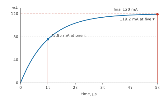
Take a coil of 10 mH whose own winding resistance is 100 Ω. Its time constant is 100 µs.
Connected to 12 V, the current will eventually settle at 120 mA, which is what the resistance allows and nothing to do with the inductance.
One time constant after switch-on the current has reached 75.85 mA, the familiar fraction of the way. After five it is at 119.2 mA and the job is done for any practical purpose.
Meanwhile the voltage across the inductor runs the other way. It takes the whole supply at the instant of switch-on and decays as the current builds, so one time constant in it is down to 4.415 V.
The R in the time constant is everything resistive in the loop, which for a coil means its own winding resistance plus any series resistor plus the source's output impedance — and for a coil with a low DCR driven from a stiff supply, the time constant can be far longer than a quick glance suggests. And the current, not the voltage, is the quantity to think about; an inductor's voltage is whatever it needs to be to make the current do what the equation says.
Measuring a time constant on the bench is easiest as a voltage. Put a small sense resistor in series with the coil, watch the voltage across it on a scope, and the trace is the current curve to scale. Drive the circuit with a square wave slow enough for the current to settle each half-cycle, and read the time to 63 %.
Engineer
Why R sits underneath, and what happens at switch-off
Apply Kirchhoff's voltage law round a loop containing a supply, a resistance and an inductance. The supply voltage is shared between the resistive drop, which is proportional to the current, and the inductive drop, which is proportional to the rate of change of that current. Written out, that is a first-order differential equation whose characteristic time is L divided by R — the combination that has to have units of time for the equation to balance. The RC case gives R times C by the same argument, which is why the resistance ends up on opposite sides of the two expressions.
The asymmetry is worth demonstrating rather than asserting:
Worked example — Ten times the resistance, ten times faster
Replace the 100 Ω coil with an otherwise identical one whose circuit resistance is 1.0 kΩ.
The time constant falls to 10 µs, a tenth of what it was.
The final current falls to 12 mA, also a tenth. Less current to reach, reached proportionally sooner. An RC circuit given ten times the resistance would have become ten times slower, and this is the single most common confusion between the two.
Switch-off is where the RL circuit becomes interesting, because the resistance in the loop is no longer the resistance that was there before. Opening a switch removes the supply and, unless something else is provided, removes the current path as well — which is the situation energy stored in an inductor covers, where the coil generates whatever voltage it takes to keep going. Provide a path, and the decay is an ordinary exponential again with a new time constant:
Worked example — A bleed resistor across the coil
Wire 1.0 kΩ across the same coil, so that the current has somewhere to go when the switch opens.
The decay loop now contains the coil's own 100 Ω plus the bleeder, so 1.1 kΩ in total, and the time constant drops to 9.09 µs.
At the instant of switch-off the coil is still carrying 120 mA, and pushing that through the bleeder produces 120 V across it.
Ten times the supply voltage, from a resistor fitted to make the circuit safe. The bleeder does its job, but the voltage it develops is one the switching device has to survive.
That trade governs every clamping decision. A large bleed resistance makes the decay fast and the voltage high; a small one makes it slow and the voltage low. A diode is the extreme low-voltage end of the same choice, holding the coil at less than a volt and letting the current take a long time to fade. Which end suits depends on whether the design cares more about speed or about the switch's voltage rating.
The model's limits are the same ones inductance carries. It treats L as a constant, which fails once the core saturates — a saturating inductor's time constant collapses along with its inductance, which is why a current trace that was curving neatly can suddenly go straight up. It treats R as a constant, whereas winding resistance rises with temperature. And it ignores the winding capacitance, which is what puts the ringing on a real switch-off waveform rather than the clean exponential the equation draws.
Professional
Where the delay actually shows up
Electromechanical parts are where RL time constants stop being an exercise and become a specification.
Worked example — A relay's release delay
A relay coil of 0.5 H with a winding resistance of 200 Ω has a time constant of 2.5 ms.
The armature does not release until the current has fallen enough for the spring to overcome the remaining magnetic pull, which takes a few time constants — so the release delay is measured in milliseconds, not microseconds, and it depends on what is fitted across the coil.
That is why the choice of clamp on a relay coil is a timing decision as well as a protection one. A plain diode gives the longest release delay, because it holds the coil at a fraction of a volt and the current takes the longest to decay. A diode with a series resistor, or a zener in the path, raises the decay voltage and shortens the delay proportionally, at the cost of demanding a switch that stands the higher voltage. Fast-release relays in production designs almost always use a zener or an RC snubber for this reason.
Inductance is rarely a constant in this material either. A relay's inductance changes as its armature moves, because the magnetic path closes, so the current trace during pull-in has a visible kink where the armature seats. That kink is genuinely useful: it is the standard way to detect, in software, that a solenoid has actually moved rather than merely been energised.
In switching converters the same time constant governs a different question. The inductor current ramps during each switch cycle, and the ramp is the early, nearly straight part of the RL exponential — nearly straight because the switching period is short compared with L over R. The ripple current follows from that ramp, and the inductor value is chosen to keep it within a chosen fraction of the average current. The time constant is doing the work even where nobody writes it down.
Long-time-constant circuits raise a different problem: the current takes so long to settle that a fault can go unnoticed. A large coil on a stiff supply can have a time constant of hundreds of milliseconds, so an overcurrent trip has to distinguish a legitimate energising ramp from a genuine short. That is why motor and solenoid drivers carry inrush blanking rather than a plain current threshold.
The time constant is also a useful measurement in its own right. A coil's inductance can be found by driving it from a known resistance and timing the current's approach — no LCR meter required, and it gives the inductance at the actual working current rather than at the meter's small-signal test level. For a part that is anywhere near saturation, those two numbers are not the same, and the one taken at the working current is the one the circuit will obey.
Common mistakes
- Expecting more resistance to slow an RL circuit down — it speeds it up. Resistance divides in the RL time constant and multiplies in the RC one.
- Thinking the inductance sets the final current — it sets only how long the current takes to get there. Resistance alone decides where it ends up.
- Counting only the resistor you fitted — the coil's own winding resistance and the source impedance are in the loop too, and for a low-DCR coil they dominate.
- Ignoring what the decay path does to the voltage — a bleed resistor large enough to give a fast release develops a voltage far above the supply when the switch opens.
- Assuming a plain flyback diode is free — it gives the longest release delay of any clamp, which matters wherever the relay's timing does.
- Trusting a small-signal inductance measurement near saturation — the inductance at the working current can be well below the meter's figure, and so can the time constant.
Frequently asked questions
What is the RL time constant?
Inductance divided by resistance, giving a time in seconds. It is how long the current in an inductive circuit takes to cover about 63 % of the distance to its final value after a switch operates.
Why does more resistance make an RL circuit faster?
Because resistance sets the final current rather than restricting the way to it. More resistance means a lower target, and a lower target is reached proportionally sooner for the same inductance.
Does the inductance affect the final current?
No. The final current is the supply voltage divided by the total resistance. Inductance decides only how long the approach takes.
What sets the time constant when the supply is switched off?
Whatever resistance the current can flow through after the switch opens. A bleed resistor across the coil adds to the winding resistance, and a larger bleeder gives a faster decay and a higher voltage.
Why does a relay with a plain flyback diode release slowly?
A diode holds the coil at a fraction of a volt, so the current decays slowly and the armature stays pulled in until it has fallen far enough. A zener or a resistor in the decay path raises the voltage and shortens the delay.