
Quick Answer
The RC time constant, τ = R × C, is how long a capacitor charging through a resistor takes to reach about 63% of its final voltage. After five time constants it is essentially fully charged (over 99%). τ sets the speed of every RC timer, filter and smoothing circuit.
Intuition
Filling a tank through a thin pipe
Charging a capacitor through a resistor is like filling a water tank through a narrow pipe. At first the tank is empty, the pressure difference is large, and water rushes in. As the tank fills, the pressure difference shrinks, so the flow slows. The fuller it gets, the slower it fills — it creeps toward full without ever quite slamming shut.
That is exactly the shape of the capacitor's voltage: fast at first, then leveling off. The time constant is nature's yardstick for this creep: after one time constant the tank is about two-thirds full; after five it's full for any practical purpose.
Here's the useful part: you choose the creep speed. Bigger tank (more capacitance) or thinner pipe (more resistance) means slower filling. That one knob — pick R, pick C, get a predictable delay — is why this humble pairing sits inside timers, blinking lights, camera flashes and the 555 timer you'll meet later.
Practitioner
The 63% rule and the five-τ rule
Ohms times farads gives seconds — a genuinely handy coincidence of units. Two rules of thumb carry most practical work:
- After 1 τ: the capacitor has covered 63.2 % of the way to its final voltage.
- After 5 τ: 99.3 % — call it done.
The percentages are universal — they don't depend on R, C or the supply voltage:
| Time | Charge reached |
|---|---|
| 1 τ | 63.2 % |
| 2 τ | 86.5 % |
| 3 τ | 95.0 % |
| 4 τ | 98.2 % |
| 5 τ | 99.3 % |
Worked example — The classic 10 kΩ / 100 nF pair
With R = 10 kΩ and C = 100 nF: τ = R × C = 1.0 ms.
Charging from a 5.0 V supply, the capacitor reaches 3.16 V after one time constant and 4.97 V after five — effectively the full supply.
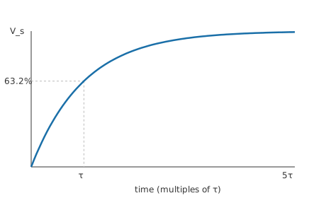
To measure τ on an oscilloscope: feed the RC with a square wave and read the time for the rising edge to cross 63% of its final level.
Engineer
Where the exponential comes from
Apply KVL around the loop: the supply voltage splits between the resistor and capacitor, V_s = iR + v_C. The capacitor's defining relation i = C·dv_C/dt turns this into a first-order differential equation: RC·dv_C/dt + v_C = V_s. Its solution, for a capacitor starting empty, is the charging law:
The product RC appears naturally as the equation's characteristic time — that's why τ = RC rather than some other combination. Setting t = τ gives the factor (1 − e⁻¹) ≈ 0.632: the 63% rule is just e doing its thing. Discharging swaps the roles and gives a pure decay:
Worked example — Reading a discharge at t = 2τ
The same capacitor, charged to 5.0 V, discharges through the same resistor. At t = 2τ its voltage is V₀·e⁻² = 0.677 V — the mirror image of the charging table's 2τ row, read from the top down instead of the bottom up.
Two things worth internalizing at this level. First, the tangent construction: if the initial charging rate continued unchanged, the capacitor would reach the full supply in exactly one τ — a neat way to estimate τ from a scope trace. Second, this same mathematics governs every first-order system — RL circuits (RL time constant), thermal warm-up, pressure equalization — so the intuition transfers far beyond capacitors, and it generalizes formally in First-Order Transient Analysis.
Professional
Why real timing circuits drift
The equation is exact; the components aren't. In design work the questions move to how wrong τ can be:
Tolerance stack. τ inherits both parts' tolerances. A ±5% resistor with a ±20% electrolytic gives a delay uncertain by roughly ±25% — fine for a power-on LED fade, useless for anything resembling accurate timing. Film or C0G/NP0 ceramic capacitors (Ceramic Capacitors & MLCC Classes) pull capacitor tolerance to ±5% or better.
Leakage and loading. The ideal equation assumes the only discharge path is your resistor. Real capacitors self-discharge (leakage), and whatever measures or uses v_C loads the node. With megohm-scale R, meter impedance and PCB leakage become part of the circuit — the classic reason a "10-second" delay measures as seven.
Dielectric absorption and ESR. Some dielectrics "remember" charge and creep back after a quick discharge — poison for sample-and-hold accuracy. ESR adds a small step at t = 0 before the exponential takes over; visible on fast edges, negligible at audio speeds.
The professional escape: ratios. The 555 astable earns its fifty-year career by timing off ratios of the supply (1/3 and 2/3 V_cc), so the supply voltage cancels and only R and C matter. When even RC tolerance is too loose, designs move to crystal-derived timing (Crystals & Ceramic Resonators) — RC for shape and smoothing, quartz for accuracy.
Common mistakes
- Treating 5τ as a magic wall — the capacitor never mathematically reaches the supply; 5τ is a convention (99.3%), and precision circuits must say what "charged" means for them.
- Forgetting the source resistance — the R in τ is everything in the charging path: source output impedance and wiring add to your resistor, which matters when R is small.
- Using an electrolytic's marked value in timing maths — ±20% tolerance plus aging makes electrolytics timekeeping liabilities; they smooth, film and C0G parts time.
- Measuring with a 1× probe on high-impedance RC nodes — the probe's own resistance and capacitance re-tune the circuit being measured (Oscilloscope Probes & 10x Attenuation).
Frequently asked questions
What does the RC time constant mean physically?
It's the time for a charging capacitor to cover 63.2% of the remaining distance to its final voltage — or for a discharging one to fall to 36.8% of where it started. It is the natural time-scale of any resistor-capacitor pair.
Why 63% and not 50%?
Because the curve is the exponential e⁻ᵗ/τ, and at t = τ that factor is e⁻¹ ≈ 0.368 — leaving 63.2% covered. The number falls out of the mathematics; it wasn't chosen.
How long until a capacitor is fully charged?
Practically, five time constants (99.3%). Strictly, never — the approach is asymptotic, so datasheets and designs specify a threshold instead of "full".
Does the time constant depend on the supply voltage?
No. A higher supply charges toward a higher target at proportionally higher current; the percentages versus time are identical. τ depends only on R and C.
Is there an equivalent for inductors?
Yes — RL circuits have τ = L ⁄ R with the same exponential behavior and the same 63%/5τ rules. See the RL time constant lesson.