
Quick Answer
Capacitance is the amount of electric charge a component takes on for each volt applied across it. Its SI unit is the farad, one coulomb per volt. A capacitor with a large capacitance accepts a lot of charge for a small change in voltage, which is what makes it useful for storing and smoothing.
Intuition
The electrical stiffness of a spring
Push on a spring and it moves. Push harder and it moves further, and the ratio between the two is what tells you which kind of spring you are holding: a stiff one barely budges under a heavy hand, a soft one travels a long way under a light one. Nobody describes a spring by how far it happens to be squashed at the moment. They describe it by how much force it takes to squash it.
A capacitor is the electrical version of that idea, and capacitance is its softness rather than its stiffness. Apply a voltage across it and charge piles up on its two plates, positive on one side and negative on the other. A capacitor with a lot of capacitance swallows a great deal of charge before its voltage has risen very far. One with very little capacitance fills up almost at once.
The unit is the farad, named after Michael Faraday, and it is defined exactly as that ratio: one farad is one coulomb of charge for every volt. The farad turns out to be an enormous unit, so enormous that ordinary components are labelled in millionths and thousand-millionths of one. A capacitor marked 100 nF holds a hundred thousand-millionths of a coulomb per volt, and that is a perfectly normal part you will find a dozen of on any circuit board.
What matters about all this is that the charge does not vanish when you take the supply away. It sits there. That is the property everything else in this department is built on, and it is what separates a capacitor from a resistor, which forgets everything the instant the current stops.
Practitioner
Reading a capacitance off the bench
The definition is directly usable as a measurement. Put a known charge on a capacitor, read the voltage it settles at, and divide:
Worked example — A capacitor identified from what it holds
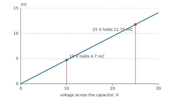
A capacitor accepts 4.7 mC of charge and settles at 10 V.
Those two figures fix the capacitance at 470 µF.
The ratio is a property of the part, not of this particular test, so it predicts the other cases too. Charging the same capacitor to 25 V instead puts 11.75 mC on it.
Values in practice span an absurd range, and the range itself is informative. Picofarads belong to radio work, to stray coupling between adjacent tracks, and to the input of a scope probe. Nanofarads do filtering and timing. Microfarads sit across supply rails and inside audio coupling paths. Millifarads and whole farads live in supercapacitors and in the reservoir capacitors of power supplies. Twelve decades separate the ends of that list, so a capacitor is never "a capacitor" the way a resistor is often just a resistor.
Reading the markings is its own small skill. Large parts print the value outright, often with a voltage rating and sometimes a polarity stripe. Small ceramic parts use a three-digit code where the last digit is a count of zeros in picofarads, so 104 means ten with four zeros after it, or 100 nF. A capacitance meter or an LCR meter settles any doubt, and is worth reaching for whenever a marking is worn or ambiguous.
The voltage rating printed beside the value is not a suggestion. It is the maximum the dielectric between the plates will tolerate before it breaks down, and exceeding it damages the part rather than merely stressing it. Derating below the rating is normal practice, and how far below depends on the family — a subject the dielectrics lesson takes up properly.
Two capacitors of identical value are not interchangeable if their dielectrics differ. Stability with temperature, behaviour under a DC bias, leakage and losses all belong to the material rather than to the number on the label, which is why a circuit that works with one part can misbehave with another of the same marked value.
Engineer
Geometry sets the farads, and the charge has to arrive somehow
Capacitance is set by geometry and by the material between the plates. For two flat plates facing each other, close enough that the field between them is essentially uniform:
Larger plates hold more charge at a given voltage, and bringing them closer raises the field for the same voltage, which pulls more charge on. The permittivity of free space, ε₀, is the constant that converts the geometry into farads.
Worked example — Two plates, and why the farad is such an awkward unit
Take two square plates of 0.0001 m² each, a centimetre on a side, separated by 100 µm of air. With ε₀ at 8.854 pF/m and a relative permittivity of 1.0 for air, the pair comes to 8.85 pF.
That is a usable trimmer capacitor and nothing more. Working backwards, reaching 1.0 µF with the same spacing and the same air gap would need plates of 11.3 m² — about the floor area of a small room.
Nobody builds capacitors that way. Every practical construction attacks one of the three terms: metallised film rolled into a cylinder to buy area in a small volume, dielectric layers a few micrometres thick to shrink the separation, and ceramic formulations with permittivities in the thousands to multiply what the geometry alone would give.
The relation between current and voltage follows from the definition. Charge on the plates is capacitance times voltage, so a changing voltage means charge is arriving or leaving, and charge per second is current. A capacitor therefore passes current in proportion to how fast its voltage is changing, and passes none at all at a steady voltage. Written as a rate of change that is the derivative form, i = C·dv/dt; measured over a finite interval it becomes an average:
Worked example — The current a ramp demands
Driving 1.0 µF from one voltage to another 2.0 V higher, taking 10 ms to do it, calls for an average current of 200 µA.
Cut the time to a tenth and the current demand goes up tenfold. That single sentence explains why fast edges on a capacitive load draw large current spikes, and why a slow ramp into the same capacitor is undemanding.
Voltage across a capacitor cannot change instantly, then, because that would require infinite current — a constraint worth carrying forward, since it governs every switching circuit later in this department. A capacitor in a settled DC circuit carries no current at all, which is why it looks like an open circuit once everything has stopped moving. The dynamics in between are the subject of capacitor charging and discharging, and the rate at which they happen is the RC time constant.
The parallel-plate formula is a model, and its limits are honest ones. It assumes the field between the plates is uniform and that nothing happens outside them, which is only approximately true — the fringing field around the edges adds capacitance the formula ignores, and the error grows as the plates get smaller relative to their spacing. It also assumes the dielectric responds instantly and identically at every frequency, which no real material does.
Professional
What the marked value is actually worth
A capacitor's label is a nominal figure, and design work is mostly about the distance between that figure and the part in front of you.
Worked example — Tolerance before anything else has gone wrong
A part marked 47 nF with a tolerance of 20 % may be anywhere from 37.6 nF to 56.4 nF when it leaves the factory.
That spread is before temperature, before ageing, and before any applied voltage has had its say. A timing circuit built on it inherits the whole of it.
Class 2 ceramics lose capacitance under DC bias, and the loss is large rather than marginal. A small-case X5R or X7R part sitting at its rated voltage routinely measures well under half its marked value, because the very permittivity that makes the part small is field-dependent. Manufacturers publish bias curves for this reason, and a decoupling design that ignores them can end up with a fraction of the capacitance the schematic claims. Class 1 dielectrics such as C0G or NP0 do not behave this way, which is why they cost more per farad and are specified wherever the value has to mean something.
Temperature moves the value as well, and the dielectric code tells you how much. The letter groups on Class 2 parts encode a working temperature range and a permitted capacitance change across it, and the permitted change for the looser grades is very wide indeed. Reading that code is a design step, not a formality, and the ceramic capacitor lesson takes the classes apart in detail.
No capacitor is only a capacitance. Its leads and internal structure add series inductance, its plates and contacts add series resistance, and its dielectric leaks a small current across the gap. Above a certain frequency the series inductance dominates and the part stops behaving capacitively altogether, which is why a large electrolytic is a poor high-frequency decoupler and why several capacitors of different sizes are often fitted in parallel. Equivalent series resistance matters wherever ripple current flows, since it turns that current into heat inside the part.
Ageing is a real mechanism in Class 2 ceramics: capacitance falls logarithmically with time after manufacture, and heating the part above its Curie point resets the clock. Electrolytics dry out instead, losing capacitance and gaining ESR as they go, faster at high temperature. Both are predictable enough to design around, and both catch people who measure a board at build time and never again — see capacitor failure modes.
Choosing a part therefore starts with what the value has to do. If it only has to be big enough — bulk energy storage, supply reservoir — a loose, cheap, high-density family is the right answer. If the value sets a frequency or a delay, the dielectric matters more than the number, and a stable Class 1 part or a film capacitor is worth the size and the money.
Common mistakes
- Treating the marked value as the actual value — tolerance, temperature, DC bias and ageing all move it, and on Class 2 ceramics they can move it a long way.
- Ignoring the voltage rating — it is a breakdown limit for the dielectric, not a performance figure, and exceeding it destroys the part rather than derating it.
- Assuming two parts of the same value are interchangeable — the dielectric decides stability, leakage, losses and bias behaviour, none of which appear in the capacitance figure.
- Expecting a capacitor to pass DC — current flows only while the voltage is changing; a settled DC circuit sees an open circuit.
- Fitting an electrolytic backwards — polarised parts fail, sometimes violently, when reverse-biased, and the stripe marks the negative terminal.
- Using one large capacitor where several sizes were needed — series inductance makes a big part useless at high frequency, whatever its capacitance says.
Frequently asked questions
What is capacitance?
The charge a component takes on per volt applied across it. One farad is one coulomb per volt, which makes the farad an unusually large unit — ordinary parts are marked in picofarads, nanofarads and microfarads.
Why is the farad such a large unit?
It falls out of the SI definitions of the coulomb and the volt rather than from anything convenient. Two plates a centimetre square and a tenth of a millimetre apart come to only a few picofarads, so a one-farad part needs either an enormous effective area or a very high-permittivity dielectric.
Does a capacitor conduct?
Not across the dielectric. Current flows into one plate and out of the other while the voltage is changing, which looks like conduction from outside, but at a steady voltage the current stops.
What decides a capacitor's value?
Plate area, the separation between the plates, and the permittivity of the material between them. Larger area and closer plates both raise it; a high-permittivity dielectric multiplies whatever the geometry gives.
Why does my capacitor measure lower than its marking?
Tolerance accounts for some of it. On Class 2 ceramics, DC bias accounts for much more — many such parts measure well under half their marked value when working at their rated voltage.
Knowledge check
A capacitor holds 60 µC of charge at 12 V. What is its capacitance? (Show answer)
Two plates are moved twice as far apart. What happens to the capacitance? (Show answer)
How much average current flows while a 470 µF capacitor is ramped 5 V in half a second? (Show answer)
Why does a capacitor block DC but pass a changing signal? (Show answer)
You need a part whose value must stay put across temperature and applied bias. Which dielectric class? (Show answer)
References
- CODATA / NIST, Fundamental Physical Constants: the electric constant ε₀ (vacuum permittivity), quoted here to four significant figures.