
Quick Answer
A capacitor is a component that holds charge in proportion to the voltage across it, built as two conductors separated by an insulator. The ratio of charge to voltage is its capacitance. As a part you buy, that value comes with a voltage rating, a tolerance, a dielectric and a package, and every one of them matters.
Intuition
A spring, not a tank
Wind a spring and it pushes back. Wind it further and it pushes back harder, in step, until you let go and it gives everything back. Nothing has been consumed. The spring has no capacity in the sense a bucket does; what it has is a stiffness, a fixed exchange rate between how far you have pushed it and how hard it resists.
A capacitor works the same way, with charge instead of displacement. Push charge onto one plate and a voltage appears. Push twice as much and you get twice the voltage. Let it go and the charge comes back out. Capacitance is that exchange rate, and charging and discharging is the spring being wound and released.
The tank picture that turns up in every introduction is not wrong, but it quietly suggests the wrong thing: that a capacitor fills up and stops. It does not. It gets harder to push against, without limit, until something breaks. What actually stops you is the voltage rating on the side of the part, and that is a property of the insulation rather than of the physics.
This lesson is about the part rather than the principle. A 2.2 µF capacitor is not a quantity; it is an object with a size, a price, a dielectric, a rated voltage and a set of things it is bad at. Everything after this in the department is a family of that object, and this is the page they all build on.
Practitioner
Reading the catalogue line
Four things identify a capacitor before anything else: the value, the tolerance on it, the voltage it may be worked at, and what the dielectric is made of. The first two come off the body as a printed code (markings and codes), the third is printed too, and the fourth is often only in the datasheet.
The value is the ratio the part holds between charge and voltage:
Worked example — What the part is holding at two working voltages
Take the 2.2 µF part at a working voltage of 5.0 V. The charge sitting on its plates is 11.0 µC.
Raise the working voltage to 16 V and the charge rises with it, to 35.2 µC. The capacitance has not changed and neither has the part; the ratio between the two numbers is the same at both points, which is what makes it a useful number to print on a component.
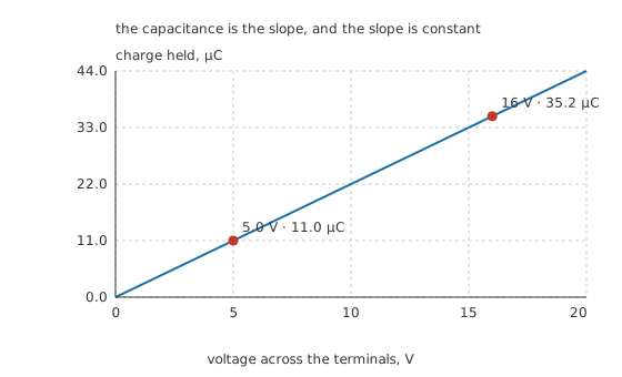
The slope is the capacitance, and the line is straight because the slope does not change.
That straight line is the whole of the component's behaviour at DC, and it is also why a capacitor is useless as a battery: to get the charge out you have to let the voltage fall, so the last of it comes out at nearly nothing.
The second relation is the one that makes capacitors interesting in a working circuit. Current into a capacitor is not set by the voltage across it but by how fast that voltage is changing:
Move the 2.2 µF part's voltage by 4.0 V over 2.0 ms and it draws 4.4 mA. Ask for the same 4.0 V in 20 µs instead and it draws 440 mA, a hundred times as much, from a part that has not changed at all.
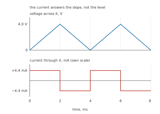
The current follows the slope of the voltage, which is why it is a square wave against a triangle.
Two capacitors combine the opposite way round from two resistors, and this catches people out for years. Side by side the plate areas add, so the capacitances add. Stacked in series the gaps add, so the value falls below either part.
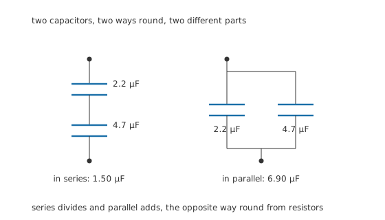
Series divides and parallel adds, which is the reverse of what resistors do.
The 2.2 µF part and a 4.7 µF part come to 1.50 µF in series and 6.90 µF in parallel. Capacitors in series and parallel works through why, and the series case has a consequence this department keeps returning to: the voltage splits across the string in inverse proportion to the values, so the smaller part takes the larger share.
Engineer
Where the value comes from, and what it costs in material
Area over gap
Three things set the capacitance: how much conductor faces how much conductor, how far apart the two are, and what is in between. Nothing else. That is a short list, and every capacitor family in this department is an argument about how to win on it.
Take the 2.2 µF part as a film capacitor: two aluminium foils 5.0 µm thick, separated by a plastic film 6.0 µm thick with a relative permittivity of 2.2, in a vacuum permittivity of 8.854 pF/m. Solve the relation backwards for the area and it comes to 0.678 square metres of facing foil. At 50 mm wide, that foil runs 13.55 metres before it is wound into something the size of a sugar cube.
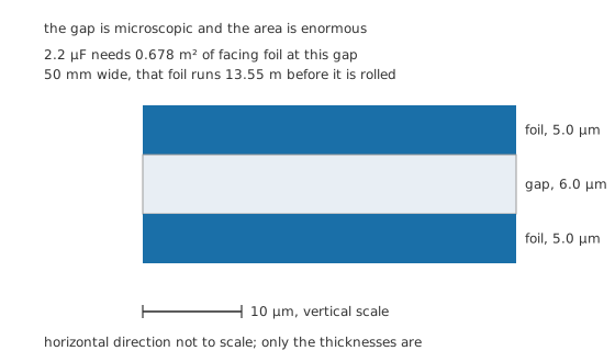
Only the thicknesses are drawn to scale; the other direction is thirteen metres of it.
That ratio is the whole engineering problem. The gap wants to be small because capacitance goes up as it shrinks, and it wants to be large because the voltage rating goes down as it shrinks. Every family in this department picks a different point on that trade, and dielectrics is where the material half of it lives.
Push the permittivity up and you buy capacitance without paying in area or gap, which is why ceramic capacitors use materials with permittivities in the thousands rather than the low single figures a plastic film offers. Push the area up by roughening the surface until it is a sponge and you get electrolytic capacitors. Push the gap down to a few atoms of oxide grown in place and you get them again, from the other direction. Film capacitors refuse all three tricks and get their stability as the reward.
More than fifteen decades of the same word
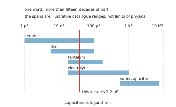
Illustrative catalogue spans, not limits of physics. The families overlap far more than their reputations suggest.
One word covers a part that tunes a radio at a picofarad and a part that runs a bus door at a kilofarad. They are not variations on a theme; they are different objects that happen to share a defining relation. A designer who reaches for "a capacitor" without naming the family has not finished specifying anything, which is why choosing the right capacitor is a lesson rather than a footnote.
What the value alone will not tell you
The number on the body is measured under stated conditions, and the conditions are doing real work. Capacitance is quoted at a test frequency and a test voltage, at a stated temperature, on a part that has been sitting undisturbed. Change any of those and the reading changes, sometimes by a factor rather than a percentage.
This is not a defect and it is not the same for every family. A class 1 ceramic or a film part will hold its value across temperature and bias to within a percent or two. A class 2 ceramic can lose most of its marked value under a working DC bias, and it is still inside its specification while it does so. The marked value is the beginning of the answer.
Professional
Three components in one package
A real capacitor is a capacitance in series with a resistance and an inductance, and the two extras come from the same material the capacitance came from: the foil, the tabs, the leads and the connection to them.
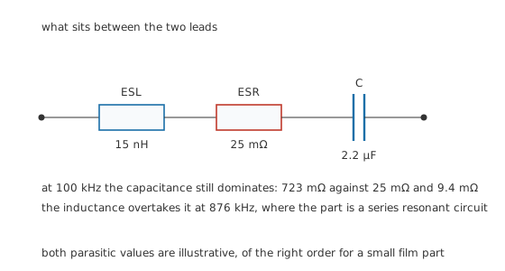
Both parasitic values are illustrative, of the right order for a small film part.
Take an illustrative 25 mΩ of series resistance and 15 nH of series inductance on the 2.2 µF part. At 100 kHz the capacitive reactance is 723 mΩ, the inductive reactance is 9.4 mΩ, and the part still behaves as its marked value with room to spare.
Keep climbing and the two reactances meet. They cancel at 876 kHz, where the only thing left between the terminals is the resistance, and above that frequency the part is an inductor with a capacitor's label on it. ESR and capacitor parasitics takes the model apart properly; impedance is the general case it sits inside.
Three consequences follow, and they are the reason this department exists.
The first is that a capacitor has a bandwidth. A part chosen for its value can be the wrong part for the job because of where its self-resonance falls, which is the whole argument in decoupling.
The second is that the series resistance turns ripple current into heat inside a sealed body. That heat is what sets the working life of an electrolytic and it is not visible anywhere in the marked value.
The third is that the voltage rating is a property of the insulation, and insulation is the thing that ages, absorbs moisture and gets punctured. Nothing about the capacitance predicts how a part fails, which is why voltage ratings and derating and failure modes are separate lessons from this one.
The trade that runs under all of it is that capacitance per unit volume and quality are bought against each other. The families that give you the most farads per cubic millimetre give you the worst tolerance, the worst temperature stability, the highest losses and the shortest life. The families that hold their value give up two or three decades of capacitance to do it. There is no part that wins both, and a designer who assumes otherwise buys the small one and finds out in the field.
Common mistakes
- Treating a capacitor as a small battery — it gives its charge back only by letting its voltage collapse, so the energy comes out at a falling voltage and most of it comes out at a voltage too low to use. That is why energy stored in a capacitor is a different question from how much charge it holds.
- Adding capacitors the way you add resistors — parallel adds and series divides, the reverse of the resistor rules. Two identical parts in series give you half the value at twice the voltage rating.
- Reading the marked value as a measurement — it is a value under stated test conditions. Bias, temperature, frequency and age all move it, and on some families they move it a long way.
- Ignoring the voltage rating because the circuit runs well below it — the rating is an insulation limit, and transients, ripple peaks and the DC level all stack against it rather than taking turns.
- Assuming the part behaves as a capacitor at any frequency — above its self-resonance it is an inductor, and no amount of extra capacitance fixes a problem caused by lead inductance.
Frequently asked questions
What is the difference between capacitance and a capacitor?
Capacitance is the property, measured in farads: how much charge a thing holds per volt across it. A capacitor is a manufactured part built to have a specified capacitance, along with a voltage rating, a tolerance, a dielectric and a package. Every conductor pair has capacitance; only some of them are capacitors.
Why do capacitors in series give less capacitance?
Because putting two in series is the same as increasing the distance between the outermost plates. Capacitance falls as the gap grows, so the pair holds less charge per volt than either part alone. The compensation is that the applied voltage divides between them, so the string tolerates more.
Does a bigger capacitor always store more energy?
Not on its own. The stored energy depends on the square of the voltage as well as on the capacitance, so a small part rated for a high voltage can beat a large part rated for a low one. A capacitance figure with no voltage beside it says nothing about energy.
What does the dielectric actually do?
Two jobs. It holds the plates apart without letting current through, which sets the voltage rating, and it polarises under the field, which multiplies the capacitance by its relative permittivity. Materials that are good at the second are usually worse at the first, and that trade is what separates the families.
Why does a capacitor stop working at high frequency?
Its own leads and internal connections are a small inductance in series with the capacitance. As frequency rises the capacitive reactance falls and the inductive reactance climbs, and where they cross the part stops being a capacitor. The crossing point depends on the package, not on the value alone.