
Quick Answer
Most small capacitors carry a three-digit code: the first two digits are the significant figures and the third counts zeros, giving the value in picofarads. A letter after it gives the tolerance. Larger parts print the value directly, and polarised parts add a mark that says which lead is which.
Intuition
A code that fits where a number will not
A car number plate carries more than an identity. Somewhere in it is the year the car was registered, encoded because there was no room to write it out. Anyone who knows the scheme reads it instantly; anyone who does not sees a random string.
Capacitor markings work the same way, and for the same reason. A chip capacitor a millimetre long has no room for "one hundred nanofarads, plus or minus ten percent, rated one hundred volts". So the industry settled on codes: a few characters that expand into a full specification once you know how they expand.
There are three schemes in common use and they overlap, which is where the trouble starts. Some parts print the value in plain figures. Some print a three-digit code. Some use a letter where the decimal point should be. And the smallest parts print nothing at all, because there is genuinely nowhere to put it.
Reading them is a five-minute skill that saves hours, and misreading them is one of the more expensive mistakes available to a beginner, because a capacitor that is wrong by a factor of ten usually still works well enough to hide.
Practitioner
The three-digit code, and the letter after it
The rule is short. Take the first two digits as the significant figures, read the third as a count of zeros, and the answer is in picofarads. Then rename it upward into nanofarads or microfarads if that reads better.
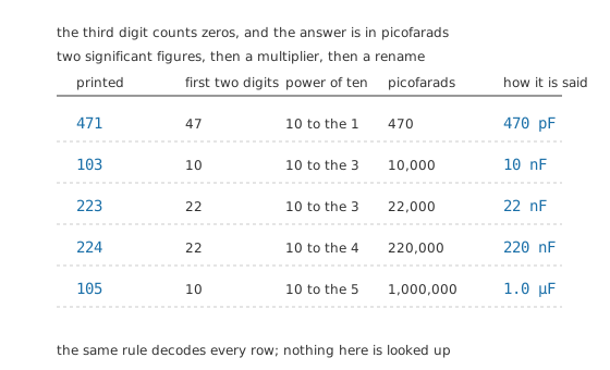
The third digit counts zeros. It is not a third significant figure, and that is the mistake people make first.
So 10 nF and 1.0 µF differ by two zeros and one printed character. 22 nF and 220 nF differ by one printed character and a factor of ten.
Worked example — Decoding 474 K and what it promises
The code 474 gives significant figures of forty-seven and four zeros after them, in picofarads. That is 470 nF.
The letter K after it is the tolerance. K means 10 % either side of nominal, so the part is allowed to measure anywhere from 423 nF to 517 nF and still be exactly what it says it is. Marked M instead, the same part could run from 376 nF to 564 nF, and marked J from 446.5 nF to 493.5 nF.
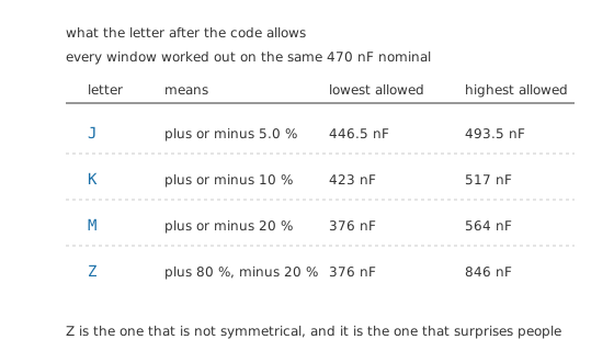
Z is the one that is not symmetrical, and it is the one that surprises people.
The letter set worth memorising is small: J is 5.0 %, K is 10 %, M is 20 %. Z is the odd one: it allows 80 % above nominal and 20 % below, so a part marked Z may hold nearly twice what its code says and still be within specification. That is not a defect, it is a grade, and it is common on the cheapest ceramic parts.
The other two schemes are easier. A part big enough prints the value in microfarads directly, so "0.47" on a film capacitor means 470 nF, not four hundred and seventy thousand of anything. And a letter can stand in for the decimal point while naming the unit at the same time: µ47 is 470 nF, 4n7 is four point seven nanofarads, 2p2 is two point two picofarads. That last convention exists because a decimal point does not survive a photocopier, a scratch or a bad print.
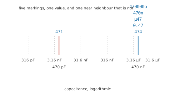
The same value, five ways of writing it, and one near neighbour that is not the same value at all.
Engineer
Why the schemes look like this, and where they collide
Picofarads as the base unit
The three-digit code counts in picofarads because it was designed when the parts it marked were small ceramic and mica capacitors, where picofarads were the working unit. Nothing about the scheme was ever extended upward; instead the parts that outgrew it started printing plain figures in microfarads. So a bare number on a capacitor means picofarads if it is a code and microfarads if it is a value, and the only way to tell is the size of the part and the number of digits.
This is a genuine ambiguity, not a failure of memory. A part printed "22" could be twenty-two picofarads, which it usually is, or twenty-two microfarads, which it can be on an electrolytic. A part printed "10" is ten picofarads on a ceramic and ten microfarads on a tantalum. The resolution is context: the case tells you the family, the family tells you the plausible range, and the range settles the unit.
What a misread digit costs
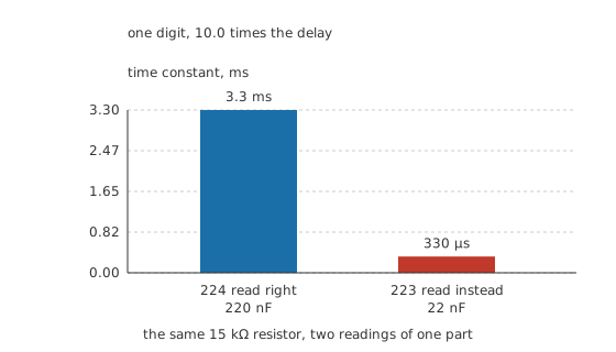
One character, one order of magnitude, on one seconds-per-pixel scale.
Put 220 nF against a 15 kΩ resistor and the time constant is 3.3 ms. Read the code as 223 instead, fit 22 nF, and the time constant becomes 330 µs, shorter by a factor of 10.0. The circuit will still start, still run, and still look right on a bench; it will simply do everything ten times faster than it was designed to. That is the characteristic shape of a capacitor error, and it is why they survive so long before anyone finds them.
Two marks that mean opposite things
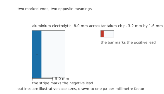
Both drawn to one px-per-millimetre factor. The marked end means the opposite thing on each.
Polarised parts carry a mark, and the two most common conventions point in opposite directions. On an aluminium electrolytic the stripe down the side runs beside the negative lead. On a tantalum capacitor the bar printed across one end marks the positive lead. Somebody who learns one convention and applies it to the other part fits it backwards, and a reversed electrolytic or tantalum part does not fail quietly.
Through-hole electrolytics carry a second clue that survives a rubbed-off stripe: the longer lead is the positive one, exactly as on an LED. It stops being a clue the moment somebody trims the leads, which is why the stripe is the one to trust and the lead length is the one to check against it.
Professional
When the marking is missing, worn or not enough
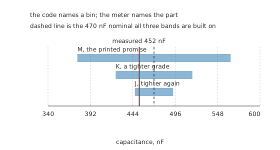
Reading the code tells you which bin the part came from. Only a meter tells you the part.
A code is a promise about a population, not a statement about the object in your hand. A part marked K promises to lie between 423 nF and 517 nF, and one real example of it measures 452 nF, which is 3.8 % below nominal. Both statements are true and only one of them is a measurement.
That distinction matters exactly when the design depends on the value rather than on its presence. A decoupling capacitor cares only that a capacitor is there. A filter corner, a timing element or an oscillator's load capacitance cares about the actual number, and for those the marking is a starting point and an LCR meter is the answer. Testing capacitors covers what else a meter can tell you about a part that the print never will.
Three things the marking commonly does not say, and where to find them instead.
The voltage rating, on the smallest parts. A 0402 chip capacitor has room for nothing at all, so its rating lives on the reel label and in the purchase order, and a part harvested from a scrap board has no recoverable rating whatsoever. Fitting an unknown chip capacitor into a mains-adjacent or high-voltage position is guesswork with a failure mode, and voltage ratings and derating explains what is at stake.
The dielectric. Two parts marked 104 K 50 V can be a C0G ceramic that holds its value across temperature and bias, and an X7R that loses a large fraction of it under working conditions. The code is identical and the parts are not interchangeable. Only the three-character dielectric code, which is printed on larger parts and buried in the ordering code on small ones, separates them, and ceramic capacitors takes that apart.
Anything about age or history. A marking is applied once, at manufacture. It does not know the part has been reverse-biased, overheated, dropped, or sitting in a drawer for fifteen years with its electrolyte slowly changing. On an aluminium electrolytic that history is often the most important thing about the part, and none of it is printed.
The working habit that follows: read the code to know what the part was sold as, check the polarity mark against the board before it goes in, and measure whenever the value is load-bearing. The marking is documentation, and documentation describes the intent rather than the object.
Common mistakes
- Reading the third digit as a significant figure — 104 is not one hundred and four of anything. It is ten with four zeros after it, in picofarads.
- Assuming a bare two-digit number is picofarads — on a ceramic it usually is, on an electrolytic it is usually microfarads. The case size settles it, not the print.
- Applying the electrolytic stripe convention to a tantalum part — the stripe marks negative on one and the bar marks positive on the other. Getting this backwards reverses the part.
- Treating a tolerance letter as a precision claim — Z allows a part to sit anywhere from a fifth below nominal to nearly double it. A part inside its tolerance can still be useless for a filter corner.
- Trusting lead length after the leads have been trimmed — the longer-lead-is-positive rule survives exactly until somebody cuts them, and then the only remaining evidence is the printed mark.
Frequently asked questions
What does 104 mean on a capacitor?
Ten, followed by four zeros, in picofarads: one hundred nanofarads. The first two digits are the significant figures and the third is the number of zeros to add. A letter after it, if there is one, gives the tolerance.
How do I tell picofarads from microfarads on an unmarked-unit capacitor?
By the size and family of the part. A three-digit code on a small ceramic is picofarads. A one- or two-figure number with a decimal point on a larger film or electrolytic part is microfarads. A part the size of a grain of rice holding twenty-two microfarads is possible but it will be a tantalum or a ceramic with a very low voltage rating, not a general-purpose part.
Which lead is positive on an electrolytic capacitor?
The one without the stripe. Aluminium electrolytics mark the negative side with a stripe or a row of minus signs down the can. Tantalum capacitors do the opposite and mark the positive end with a bar, which is the single most common way people fit one backwards.
What does the letter after the value mean?
Tolerance. J is five percent either way, K is ten, M is twenty. Z is asymmetric, allowing much more above nominal than below. The letter is a grade rather than a measurement, so it tells you the widest the part is allowed to be wrong, not how wrong it is.
Why do some capacitors have no markings at all?
Because there is no surface to print on. Chip capacitors below about a millimetre and a half long are shipped unmarked, and their identity lives on the reel and in the pick-and-place file. Once one is loose in a drawer it is unidentifiable except by measurement, and even then its voltage rating is unrecoverable.