
Quick Answer
A tantalum capacitor is a solid electrolytic: a sintered tantalum pellet, an oxide grown on it, and a solid cathode. It offers more capacitance per unit volume than any other family at these voltages, and it fails as a short rather than an open, which is why it is derated hard and fed through a limiting resistance.
Safety
A tantalum capacitor that fails does not usually go quiet. The punctured oxide becomes a short across whatever was charging it, and with a manganese dioxide cathode the part carries its own oxidiser, so an unlimited fault current can ignite it. Every figure in this lesson is arithmetic on stated component values rather than a measurement, and none of it is an instruction to test a part to destruction. Treat a tantalum on a low-impedance rail as a component that needs its fault current limited by design.
Intuition
Rated for a fall it must never take
A climbing rope carries a rating for a fall it can arrest. The number is real and the rope is tested against it, and no experienced climber treats it as a target. The rating describes the worst case the equipment survives; the discipline is to stay a long way from it, because the consequence of finding the limit is not a slightly worse day.
Tantalum capacitors are specified the same way, and they are the only family in this department where that comparison is fair. Every other capacitor here fails gently or fails open. A film part clears its own puncture and carries on. An electrolytic dries out over years and announces itself. A tantalum that is pushed too hard punctures its oxide, becomes a short across the rail, and then has to deal with whatever current that rail can supply.
Which raises an obvious question: why use them at all? Because a 47 µF tantalum rated 16 V arrives in a package a couple of millimetres across, stable, non-polarised in the ageing sense, with a working life that does not run on a clock. Nothing else in this department offers that combination, and for two decades it was the only way to get real bulk capacitance onto a dense board.
The engineering answer is not to avoid the family. It is to work it at half its rating, put something in series with it, and know what happens when it does fail.
Practitioner
Two rules that come with the part
Derate it to half
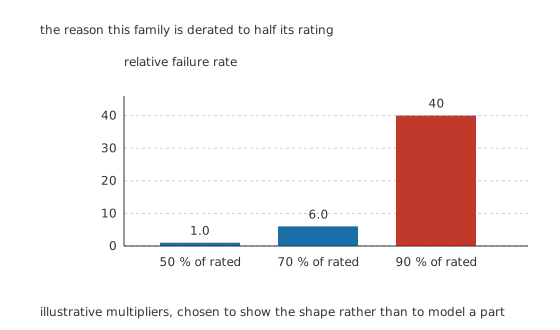
Illustrative multipliers, chosen to show the shape rather than to model a part.
The convention for this family is to run it at 50 % of its rating, so the 16 V part above becomes a 8.0 V part in practice. At 70 % the illustrative failure rate is 6.0 times higher and at 90 % it is 40 times higher, so the derating is not caution for its own sake. It is buying a factor of forty on the one property that matters.
The consequence for selection is that a tantalum's headline rating overstates what you can use, roughly by a factor of two, and comparisons against other families have to be made after that halving rather than before it.
Put something in series with it
The other rule concerns the moment a rail is switched on. A capacitor that has not been charged is a short, and the only thing limiting the current is the resistance in the loop.
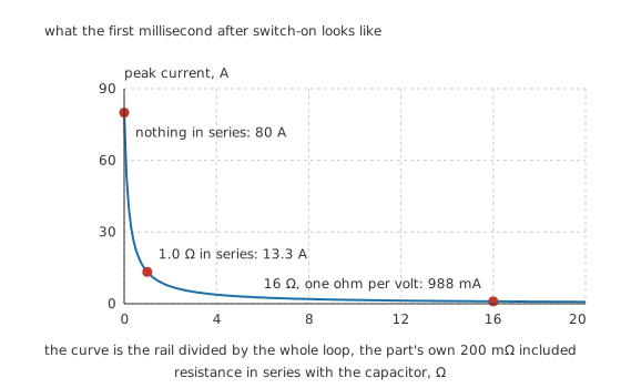
The curve is the rail divided by the whole loop, the part's own 200 mΩ included.
Worked example — Switching a tantalum onto a stiff rail
The part's own series resistance is 200 mΩ. Connect it directly across 16 V with 0.0 Ω of anything else in the loop and the peak current is 80 A.
Add 1.0 Ω and the peak falls to 13.3 A. Add the resistance the widely used rule of thumb asks for, one ohm for every volt applied, which here is 16 Ω, and the peak is 988 mA.
That is a factor of 81.0 between the first case and the last, decided entirely by a resistor that most schematics do not draw.
The surge is what damages the oxide. A momentary current spike through a weak spot heats it locally, degrades it, and either fails the part immediately or leaves it worse than it was. Parts fitted directly across a low-impedance supply fail early far more often than the same parts fed through even a small resistance, and the resistance is there for the fault case rather than for the working circuit.
Engineer
A sponge of metal with an oxide grown on it
The construction is a solid version of the aluminium electrolytic's trick, and it wins on every term.
Tantalum powder is pressed into a small block and sintered, which fuses the grains into a rigid porous sponge with an enormous internal surface. A voltage is then applied in an electrolyte and tantalum pentoxide grows over that whole surface. The oxide's relative permittivity is 27 against a vacuum permittivity of 8.854 pF/m, three times what aluminium oxide offers, and it forms at roughly 1.7 nm/V for the voltage it is grown at. Formed at an illustrative 3.0 times the rated voltage, the dielectric on the 16 V part is 81.6 nm thick.
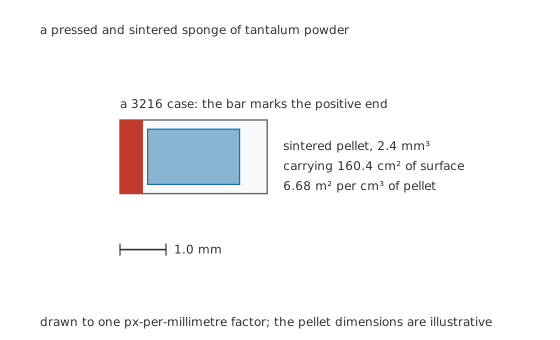
A pressed and sintered sponge of tantalum powder, with the polarity bar at the positive end.
Reaching 47 µF across that oxide takes 160.4 square centimetres of surface, and it is folded into a pellet of 2.4 cubic millimetres: 6.68 square metres of working surface in every cubic centimetre of pellet.
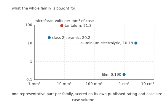
One representative part per family, scored on its own published rating and case size.
Scored as microfarad-volts per cubic millimetre of case, the tantalum reaches 91.8 in 8.192 cubic millimetres. The class 2 ceramic manages 20.2 in 3.125, the aluminium electrolytic 10.19 in 2.4544 k, and the film part 0.190 in 990. The tantalum leads the ceramic by 4.55 times and the film part by more than two decades.
Why the fault does not clear
The cathode is where the two versions of this family part company.
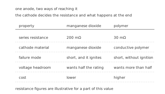
One anode, two ways of reaching it. The cathode decides the resistance and what happens at the end.
The traditional cathode is manganese dioxide, impregnated into the pellet and fired. It is a semiconductor, which is why the traditional part's series resistance sits around 200 mΩ, and it has a property that is deliberate: at a small fault the local current heats the manganese dioxide and converts it to a lower oxide that conducts far worse, plugging the fault. That is a genuine healing mechanism and it works for small faults.
At a large fault it does not work, because the current arrives faster than the conversion can plug it. Then the part stays a short, and the manganese dioxide is an oxidiser sitting in intimate contact with a fine metal powder that burns readily. That is the ignition mechanism, and it is the reason this lesson carries a safety callout that the other family lessons do not.
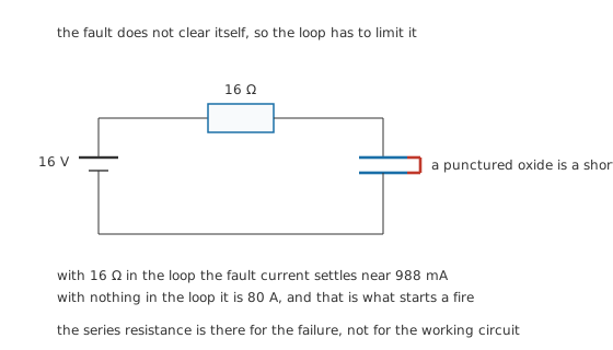
The series resistance is there for the failure, not for the working circuit.
The polymer version replaces the manganese dioxide with a conductive polymer. Series resistance falls to an illustrative 30 mΩ, the healing mechanism is different and weaker, and the ignition mechanism is gone because there is no oxidiser. A polymer tantalum that fails still fails as a short; it simply does so without a flame.
Professional
Working with the family rather than around it
Four habits cover almost everything.
Halve the rating, then choose. A part on a 3.3 V rail wants a rating of at least 10 V, and one on a 5 V rail wants 16 V. Because capacitance falls as rating rises within a case size, that halving is the real cost of using this family and it should be paid before comparing packages.
Limit the loop. Something in series, whether a deliberate resistor, a soft-start, a ferrite or simply the resistance of a long supply trace, changes the surge from a stress into an event. Parts fed from a bench supply through a metre of wire behave very differently from the same parts across an output capacitor bank.
Prefer polymer where the failure would matter. The lower series resistance is usually why people reach for polymer parts, but the removal of the ignition mechanism is the better reason. Where a fire would be a safety problem rather than a repair, polymer tantalum or a ceramic bank is the honest choice.
Never reverse one, even briefly. Aluminium electrolytics tolerate a few tenths of a volt the wrong way. Tantalums tolerate very little, and a reverse-biased tantalum degrades permanently even if it does not fail at once. The polarity bar marks the positive end, which is the opposite of the aluminium convention and a routine source of mistakes; markings and codes sets the two conventions side by side.
Where the family is losing ground, and where it is not
Class 2 ceramics have taken most of the low-voltage decoupling that tantalums used to hold, because a 10 µF ceramic in an 0805 costs less and cannot catch fire. That the ceramic delivers a fraction of its marked value under bias is a real qualification, and the charge-density figure above is computed on marked values rather than effective ones, so it flatters the ceramic. Even so, the direction of travel is clear.
Where the family still wins is where a stable, compact, ripple-tolerant bulk capacitance is needed at 10 to 50 volts and a ceramic bank would be twenty parts. Polymer tantalums in particular sit in a genuinely useful place: much lower series resistance than an aluminium electrolytic, far more capacitance per package than a ceramic, no drying and no bias collapse.
The question to answer before specifying one is not whether it fits. It is what the rail can deliver into a short, and whether that would be acceptable. Choosing the right capacitor works through the order in which to ask.
Common mistakes
- Using a tantalum at its rated voltage — the convention is half, and the illustrative failure rate at ninety percent of rating is forty times what it is at fifty.
- Connecting one directly across a low-impedance supply — with nothing in the loop but the part's own resistance the switch-on surge is tens of amps, and it is the surge that damages the oxide.
- Reading the polarity bar as an electrolytic's stripe — the bar marks the positive end on a tantalum, the opposite of the aluminium convention. Reversing one damages it permanently.
- Treating polymer and manganese dioxide parts as interchangeable — they differ in series resistance by nearly an order of magnitude and in what happens at a large fault. Only one of them can ignite.
- Comparing marked capacitance across families — a tantalum delivers its marked value under bias and a class 2 ceramic does not, so a like-for-like comparison has to use the effective value at the working voltage.
Frequently asked questions
Why do tantalum capacitors catch fire?
Because the traditional cathode is manganese dioxide, which is an oxidiser, and the anode is finely divided tantalum, which burns. If the oxide is punctured and the supply can deliver a large fault current, the local heating has both fuel and oxygen available. Polymer-cathode tantalums have no oxidiser and do not do this, although they still fail as a short.
How much should a tantalum capacitor be derated?
The usual convention is to work it at half its rated voltage, so a 16 V part is used on rails up to about 8 V. The failure rate climbs steeply with the working fraction, and derating is by far the cheapest reliability improvement available for this family.
Why does a tantalum need a resistor in series?
To limit the current at switch-on and at a fault. An uncharged capacitor is a short, so the peak current is set by the loop resistance alone, and a stiff rail can drive tens of amps through a part whose own resistance is a fraction of an ohm. A widely used rule of thumb asks for about one ohm for every volt applied.
Which end of a tantalum capacitor is positive?
The end with the bar or stripe printed across it. This is the opposite of the aluminium electrolytic convention, where the stripe marks the negative side, and applying one convention to the other part is one of the most common ways of fitting a capacitor backwards.
Are polymer tantalums better than manganese dioxide ones?
For most purposes yes, and for two separate reasons: much lower series resistance, and no ignition mechanism at a large fault. They cost more, and they still fail as a short rather than an open, so the derating and the series limiting are both still required.