
Quick Answer
An aluminium electrolytic capacitor gets its value from an etched foil and an oxide layer grown a few tens of nanometres thick, wetted by a liquid electrolyte. That construction buys more capacitance per penny than anything else, and it costs polarity, a limited working life, and a strong dislike of heat.
Intuition
A wet cell that dries out on the shelf
Every other capacitor in this department is a dry object. Foil and plastic, ceramic and metal, fired or wound and then sealed. An aluminium electrolytic is not. Inside the can is a liquid, and the part works because that liquid is there.
That single fact explains almost everything about the family. It is why the part is cheap: the dielectric is not a manufactured film but a layer of oxide grown on the foil by the applied voltage itself, and growing something is cheaper than laying it down. It is why the part is polarised: the oxide is grown in one direction and reverse voltage strips it. And it is why the part has a working life measured in hours rather than in decades, because a liquid in a sealed aluminium can slowly leaves, and when enough of it has gone the capacitor stops being one.
A shelf full of stock illustrates the point better than any specification does. A resistor bought in 1990 works. A film capacitor bought in 1990 works. An electrolytic bought in 1990 has been quietly drying since the day it was made, and the datasheet said how long that would take.
What you get for accepting all this is a 1.0 mF capacitor rated 25 V in a can the size of a thumbnail, for a few pence. Nothing else on the market comes close, which is why the family has survived every attempt to replace it.
Practitioner
The number a datasheet leads with, and the one that matters
Every electrolytic datasheet carries a line that no other capacitor family needs: a number of hours, at a temperature. Two thousand hours at 105 °C, five thousand at 85 °C, and so on. That is the endurance rating, and it is not a warranty period. It is a measured point on a curve.
The rule the industry uses to move along that curve is simple: every 10 °C the part runs cooler, the life doubles. The mechanism behind it is a chemical process whose rate roughly halves for the same interval, and the arithmetic that follows is startling.
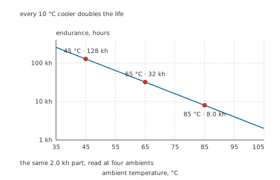
Every 10 °C cooler doubles the life, so on a logarithmic axis the line is straight.
Worked example — What 2000 hours at 105 °C actually buys
The part is rated 2.0 kh at 105 °C. On its own that reads like eighty-three days, which would make the whole family unusable.
Run it at 85 °C instead and the endurance is 8.0 kh. At 65 °C it is 32 kh. At 45 °C, which is what a well-ventilated enclosure actually reaches, it is 128 kh: 14.6 years of continuous running.
The rating did not change and neither did the part. What changed is where it was fitted.
There is a second heat source, and it is the one designers forget because it is not in the enclosure.
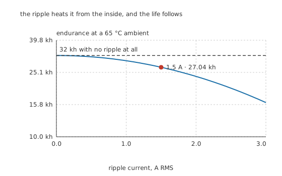
The heat is generated inside the can, where no external measurement reaches it.
Ripple current crossing the part's own 60 mΩ of series resistance dissipates power inside the sealed body. At 1.5 A that is 135 mW, and against an illustrative thermal resistance of 18 °C/W it lifts the core 2.43 °C to 67.43 °C. The endurance falls from 32 kh to 27.04 kh, a loss of 4.96 kh from a temperature rise a thermometer on the outside of the can would barely see.
Which is why a ripple-current rating sits beside the endurance rating on the same datasheet line, and why ESR is the property this family is judged on.
Engineer
Growing a dielectric instead of making one
Where the capacitance comes from
Two tricks, applied together, are what let a thumbnail hold a millifarad.
The first is the oxide. Aluminium in contact with a suitable electrolyte grows a layer of aluminium oxide when a voltage is applied across it, and the layer's thickness is set by that voltage: roughly 1.4 nm/V for the voltage it is formed at. Manufacturers form the oxide above the rated voltage, by an illustrative factor of 1.3, so the finished dielectric on a 25 V part is about 45.5 nm thick. Compare that with the six micrometres a film capacitor needs and the advantage is more than two decades of gap.
The second is etching. The foil is chemically etched into a sponge before the oxide is grown, so the surface that faces the electrolyte is enormously larger than the sheet it was cut from. An illustrative gain of 80 is ordinary for a low-voltage part.
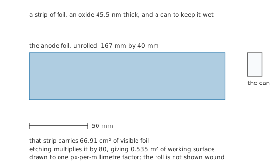
Etching multiplies that visible area by 80, giving 0.535 m² of working surface.
Put the two together. Reaching 1.0 mF across 45.5 nm of oxide with a relative permittivity of 9.6 and a vacuum permittivity of 8.854 pF/m takes 0.535 square metres of surface. Divided by the etch gain, that is 66.91 square centimetres of ordinary foil, which at 40 mm wide is 167 mm of strip: a piece the size of a postcard, rolled into a can 12.5 mm across and 20 mm tall.
Why the electrolyte has to be there
The etched surface is a sponge, and no solid conductor can be pressed into a sponge closely enough to follow every crevice. So the second plate is not solid. It is the electrolyte itself, soaked through a paper separator, reaching into the etched surface everywhere the oxide goes. The second foil in the roll is not the other plate at all; it is only the connection to the electrolyte.
Three consequences follow directly, and each of them is a defining property of the family.
Polarity is structural. The oxide exists because the applied voltage keeps it there. Reverse the voltage and the same electrochemistry that grew it strips it, leakage climbs, the current heats the electrolyte, and the electrolyte boils.
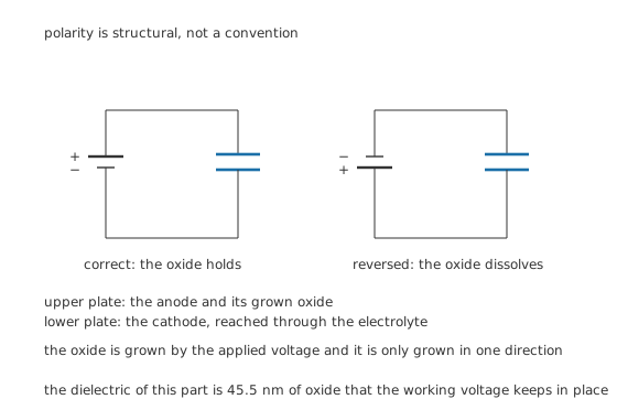
The oxide is grown by the applied voltage, and it is only grown in one direction.
The series resistance is high and it follows the liquid. Current reaching the etched surface travels through an ionic liquid in a paper separator, which is a far worse conductor than any metal. That is where most of an electrolytic's ESR lives, and it is why the figure climbs so sharply in the cold.
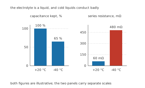
Both panels carry their own scale. Both effects follow the electrolyte.
At -40 °C an illustrative part keeps 65 % of its capacitance while its resistance rises by 8.0 times, to 480 mΩ. A supply that starts happily on a bench can fail to start outdoors in winter for no other reason.
The part can be repaired by using it. An electrolytic that has sat unpowered for years has a partly degraded oxide and will draw a large leakage current if a rated voltage is applied suddenly. Brought up slowly through a current limit, the leakage re-forms the oxide and the part recovers. That is reforming, it is a real and standard practice for stored equipment, and no other capacitor family has anything like it.
Professional
Wear-out, and how it announces itself
An electrolytic does not usually fail suddenly. It wears out, and it wears out in a specific direction: the electrolyte escapes through the rubber end seal as vapour, the remaining liquid becomes less conductive, so the capacitance falls and the series resistance rises. Both drift together, both accelerate as the part gets hotter, and the part is conventionally called worn out when the capacitance has fallen by a fifth or the resistance has doubled.
That failure shape is a gift, because it is measurable before it is fatal. A power supply that has become unreliable under load, an amplifier that has developed hum, a monitor that takes several attempts to start: all three are the signature of capacitance lost and resistance gained, and all three can be confirmed with a meter rather than guessed at. Testing capacitors is where that is done, and failure modes and ageing follows the mechanism further.
The vent, and why it is a cross
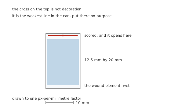
The weakest line in the can, put there on purpose.
Sometimes the electrolyte does not leave slowly. Reverse voltage, a large overvoltage or a hard overload boils it, and the pressure inside a sealed aluminium tube climbs fast. The scored cross on the top of the can is thinner than the metal around it, so it splits first and the pressure vents upward. Without it the weakest point would be the rubber bung in the base, and the part would leave the board.
Two practical rules come from that. Never fit an electrolytic where its top face is hard against something, because a blocked vent has to find another way out. And treat a bulged top as a part that has already told you what it is going to do next.
Where the family still wins, and where it does not
The advantage is capacitance per unit cost and capacitance per unit volume at values a ceramic cannot reach without a fistful of parts. Bulk energy storage, mains smoothing after a rectifier, holdup across a brownout, the reservoir in front of a regulator: all of these want hundreds or thousands of microfarads at tens of volts, and nothing else offers them at the price.
The disadvantages are the whole of the rest of this lesson. High series resistance, a life that runs on a clock, poor cold behaviour, polarity, and a tolerance that is loose from the start and gets looser. Against those, polymer aluminium parts replace the liquid with a solid conductive polymer and remove most of the resistance and most of the drying, at the cost of a lower voltage rating and a higher price, and tantalum parts take the same idea in another direction with a failure mode that needs its own respect.
The sizing habit worth carrying: pick the value the circuit needs, then pick the ripple rating the circuit demands, then check the endurance at the temperature the part will actually sit at rather than the one on the front of the datasheet. Two of those three are usually met by a part far larger than the value alone would suggest, and that is not waste. Choosing the right capacitor works through the order.
Common mistakes
- Reading the endurance rating as a product lifetime — it is hours at a stated temperature. Fitted twenty degrees cooler the same part lasts four times as long, and twenty degrees hotter it lasts a quarter as long.
- Ignoring ripple current because the ambient is comfortable — the heat that matters is generated inside the can, and a modest temperature rise there costs thousands of hours.
- Fitting one reversed and assuming it will be obvious — a reversed electrolytic can sit quietly for minutes while its oxide dissolves, then vent without further warning.
- Blocking the vent — a can pressed against a heatsink, a chassis or a cable tie has to release its pressure somewhere else, and the base seal is the alternative.
- Applying full rated voltage to old stock — an electrolytic that has been unpowered for years has a degraded oxide. Bringing it up slowly through a current limit lets it re-form; slamming it on does not.
Frequently asked questions
Why are electrolytic capacitors polarised?
Because the dielectric is an oxide layer grown on the anode foil by the applied voltage itself, and it is only grown in one direction. Reverse the voltage and the same electrochemistry strips the oxide, leakage rises, the electrolyte heats and the part vents.
How long does an electrolytic capacitor last?
It depends almost entirely on how hot it runs. The datasheet gives hours at a stated temperature, and the working figure roughly doubles for every ten degrees cooler. A part rated 2000 hours at 105 °C reaches around 128 000 hours at 45 °C, which is over fourteen years of continuous running.
What makes a capacitor bulge at the top?
Pressure inside the can. Something has boiled the electrolyte, usually reverse voltage, overvoltage, excessive ripple current or simple old age at a high temperature. The scored cross on the top is designed to split under that pressure, and a bulge means it is on its way there.
Why does a device work badly when cold and then improve?
The electrolyte is a liquid carrying ions, and it conducts worse as it cools. The capacitance falls and the series resistance rises together, sometimes by a large factor, so a supply that is marginal at room temperature can fail to start in the cold and recover once its own heat has warmed the capacitors.
Can old stock electrolytics be used?
Often, if they are reformed first. Applying a rated voltage through a current limit and raising it slowly lets the oxide layer rebuild, and the leakage current falls as it does. Applying full voltage directly to a part that has been unpowered for years can destroy it.