
Quick Answer
Equivalent series resistance is the loss a real capacitor puts in series with its capacitance, and equivalent series inductance is the inductance its structure adds. Together they set a floor under the part's impedance, turn ripple current into heat inside the case, and fix the frequency above which the part stops behaving as a capacitor.
Intuition
Money in the account, and a limit on the counter
An account can hold a large balance and still restrict what you can take out in a day. The balance says how much is there; the daily limit says how fast you can get at it. Somebody who needs a small amount immediately is better served by an account with a low balance and no limit than by a large one with a strict counter, and a fee on each withdrawal makes the point sharper still.
A capacitor has both numbers. Its capacitance is the balance. Its equivalent series resistance, always written ESR, is the limit at the counter: a real resistance in the path between the terminals and the charge, so current cannot arrive or leave without a voltage being lost across it. And there is a fee. Every ampere that crosses that resistance leaves heat behind, inside a sealed body that has to get rid of it.
There is a second restriction of the same kind. The foil, the tabs and the leads form a loop, and a loop is an inductance. That equivalent series inductance, ESL, does nothing at low frequency and eventually does everything.
Neither of these is a defect and neither can be designed away. They are what the part is made of, seen from the terminals. The whole of this lesson is about the working consequence: a 220 µF capacitor rated 35 V is not a 220 µF capacitor at every frequency, and the datasheet line that tells you where it stops being one is the ESR figure and the package, not the capacitance.
Practitioner
The curve that says everything
Sweep a real capacitor's impedance across frequency and it draws a V. Three different elements own three different stretches of it, and the part is only a capacitor along the first.
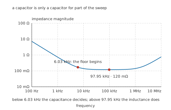
Below the first crossing the capacitance decides; above the second, the inductance does.
At 100 Hz the capacitive reactance is 7.23 Ω, sixty-odd times the 120 mΩ of resistance, so the resistance is invisible and the part behaves exactly as its marked value. Climb, and the reactance falls while the resistance does not. They meet at 6.03 kHz, and from there the impedance stops falling and sits on a floor set entirely by the ESR.
Keep going and the inductance arrives. At 97.95 kHz the inductive and capacitive reactances are equal and opposite, they cancel, and the impedance touches its minimum of 120 mΩ, which is the ESR and nothing else. That frequency is the part's self-resonance.
Above it the part is an inductor. By 10 MHz the inductive reactance has reached 754 mΩ, six times the impedance the part had at resonance, and adding more capacitance would not lower it by a millivolt.
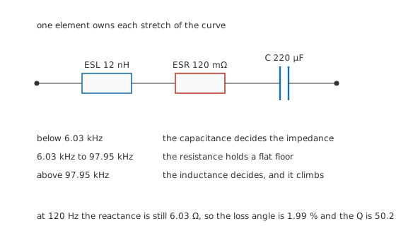
One element owns each stretch, which is why the datasheet quotes all three.
Datasheets often give the loss as a dissipation factor rather than as an ESR. The two carry the same information: the dissipation factor is the ratio of the resistance to the reactance at a stated frequency, so it depends on where it was measured and an ESR does not.
Worked example — Turning a dissipation factor back into an ESR
At 120 Hz, the frequency this class of part is conventionally measured at, the reactance of 220 µF is 6.03 Ω.
With 120 mΩ of series resistance, the loss comes to 1.99 % of the reactance, which is the dissipation factor. Its reciprocal, the quality factor, is 50.2.
Both numbers describe the same part. Quoted without their measurement frequency, neither means anything at all, because the reactance in the denominator changes with every decade.
Engineer
Where the resistance actually is
ESR is not one thing. It is the sum of every resistance the current meets between one terminal and the other, and in an aluminium electrolytic those live in three distinct places.
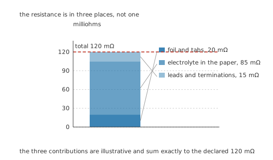
Illustrative contributions, summing exactly to the declared total. The electrolyte is the large one.
The foil and the tabs welded to it contribute 20 mΩ, and that part behaves like any other piece of aluminium. The leads and their terminations contribute 15 mΩ. The dominant term, 85 mΩ, is the electrolyte soaked through the paper separator, because a liquid carrying ions is a far worse conductor than a metal. Together they come to 120 mΩ.
That breakdown explains two behaviours that otherwise look arbitrary.
ESR rises steeply in the cold. The electrolyte's conductivity falls as it cools, and it is the largest of the three terms, so the whole figure follows it. A part measured comfortably at room temperature can have several times the resistance at twenty below, which is why cold-start behaviour is specified separately for anything intended to work outdoors.
ESR falls as the part gets bigger. A physically larger can holds more foil in parallel and a shorter path through the electrolyte, so a higher-capacitance part of the same family usually has a lower ESR. That is why designers sometimes fit far more capacitance than the circuit needs: they are buying the resistance, and the capacitance comes along with it.
The other families put their resistance somewhere else entirely. A polymer electrolytic replaces the liquid with a conductive polymer and removes most of the middle bar. A ceramic has no separator at all, only fired dielectric between electrodes, so its resistance is electrode metal and terminations. A tantalum with a manganese dioxide cathode has a semiconductor in the path, and pays for it.
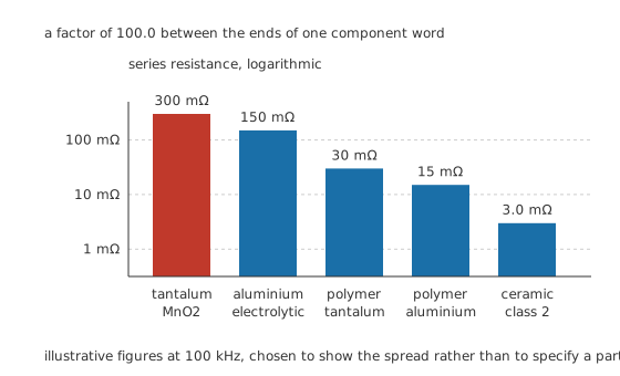
A factor of 100 across one component word. The figures are illustrative and the spread is the point.
At 100 kHz, an aluminium electrolytic sits around 150 mΩ and a tantalum with a manganese dioxide cathode around 300 mΩ, while the polymer versions of the same two families reach 15 mΩ and 30 mΩ, and a class 2 ceramic gets to 3.0 mΩ. The ends of that list differ by a factor of 100.0, which is a wider spread than the capacitance values in this department cover within any one family.
Professional
What it costs, and what to do about it
Heat, and the square law behind it
Ripple current crossing the ESR dissipates power inside a sealed body that can only lose heat through its case and leads.
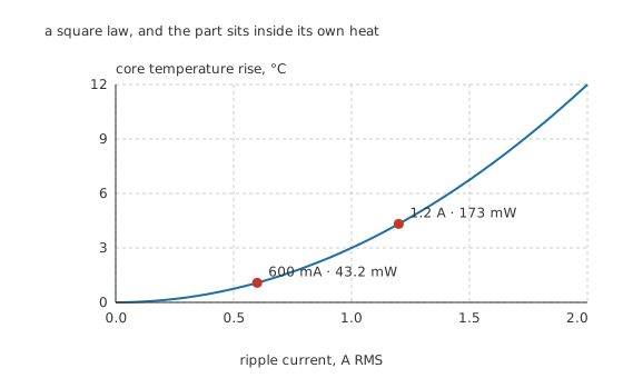
A square law. Doubling the ripple quadruples the heat.
Run 600 mA through the part and it dissipates 43.2 mW, which is nothing. Double the current to 1.2 A and the dissipation is 173 mW, four times as much, and against an illustrative thermal resistance of 25 °C/W that lifts the core 4.32 °C above everything around it. That rise is why a ripple-current rating exists at all, and why it is quoted at a stated frequency and temperature: the current is heating the part from a place no external measurement can reach. For an electrolytic that internal temperature is the single thing that sets its working life, and failure modes and ageing follows what happens next.
The inductance is a package property
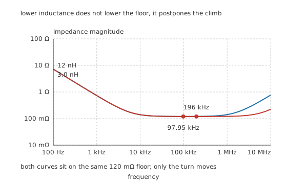
Lower inductance does not lower the floor. It postpones the climb.
Cut the series inductance from 12 nH to 3.0 nH and the self-resonance moves from 97.95 kHz to 196 kHz. The floor does not move at all, because the floor is the resistance. The two figures are bought separately: a shorter, wider current path buys inductance, a better conductor in the path buys resistance, and a part can be good at one and poor at the other.
This is also why the inductance is a property of the package rather than of the value. Two parts of the same capacitance in different case sizes have measurably different self-resonant frequencies, and the smaller one usually wins. It is the argument that decides decoupling, where the value matters far less than where the impedance floor sits and how far it extends.
What paralleling does, and does not, do
Putting capacitors in parallel divides both parasitics: two identical parts give half the ESR and half the ESL, four give a quarter. That is the standard way of getting a low impedance out of ordinary parts, and it works.
What it cannot do is fill the gap between two parts of very different value. A bulk part and a small ceramic in parallel each hold their own resonance, and between them sits a frequency where one is already inductive and the other is not yet capacitive. The combination there is worse than either part alone, which is not obvious from the schematic and is very obvious on a measurement.
The cost of a low-ESR part
A low-ESR part is not a strictly better part, and the trade is worth stating plainly. Polymer electrolytics achieve their resistance with a solid conductive cathode, and they typically carry a lower voltage rating and a higher leakage current than the liquid parts they replace. Ceramics reach the lowest resistance of all and pay for it in capacitance loss under DC bias and in mechanical fragility. Very low ESR also removes damping: a capacitor with almost no series resistance can ring with the inductance of the wiring feeding it, and in a supply that has just been switched on the resulting overshoot has damaged parts downstream. Sometimes the resistance was doing something useful.
The working habit is to read three numbers rather than one. The capacitance says how much charge is available. The ESR says how fast it can be delivered and how much heat that costs. The self-resonance says up to what frequency any of it is true. Choosing the right capacitor puts the three together.
Common mistakes
- Quoting a dissipation factor without its frequency — the figure is a ratio against a reactance that changes with every decade, so the same part has many different dissipation factors and only one ESR curve.
- Assuming more capacitance means lower impedance — above the part's self-resonance the impedance is set by inductance, and a larger part usually has more of it. Adding capacitance there makes things worse.
- Reading a ripple-current rating as a fixed number — it is stated at a frequency and an ambient temperature. At a different frequency the ESR is different, and at a different temperature the permitted rise is different.
- Measuring ESR at the wrong frequency — a meter that tests at 120 Hz reads a different resistance from one testing at 100 kHz, and for a switching supply's capacitor the low-frequency figure is not the one that matters.
- Treating very low ESR as free — it removes damping as well as loss, and an undamped capacitor can ring with the wiring inductance in front of it.
Frequently asked questions
What is ESR in a capacitor?
Equivalent series resistance: a single resistance that stands for every loss in the part, placed in series with the ideal capacitance. It comes from the electrodes, the electrolyte or dielectric, and the terminations. It sets the lowest impedance the part can reach and it converts ripple current into heat inside the case.
Why does ESR matter more at high frequency?
Because the capacitive reactance falls with frequency while the resistance does not. At low frequency the reactance is so much larger that the resistance is irrelevant; once they are comparable, the resistance sets the impedance, and from there onward more capacitance changes nothing.
What is a capacitor's self-resonant frequency?
The frequency at which its series inductance and its capacitance have equal and opposite reactance, so they cancel and only the ESR is left. Below it the part is capacitive, above it inductive. It depends on the package geometry as much as on the value.
Does a low-ESR capacitor always perform better?
No. It delivers current faster and runs cooler under ripple, which is usually what you want, but very low series resistance also removes damping and can let the part ring with the inductance feeding it. Low-ESR families also tend to trade away voltage rating, leakage or mechanical robustness.
Why does ESR rise when a capacitor gets cold?
In an aluminium electrolytic the largest single contribution is the electrolyte, and its conductivity falls as it cools. Because that term dominates the total, the whole figure follows the temperature of the liquid rather than of the metal.