
Quick Answer
A capacitor's voltage rating is the highest voltage its insulation is qualified to hold, not a voltage it is meant to work at. DC level, rail tolerance, ripple and transients all stack against it at once, so working parts are chosen with deliberate headroom rather than run near the number printed on them.
Intuition
The number on the lift
A passenger lift carries a plate stating how much it may hold. Nobody reads that as an instruction to load it to the plate. It is the point at which the engineering stops being guaranteed, and the sensible operating range is somewhere comfortably below it.
A capacitor's voltage rating works the same way, with one difference that matters: the lift only carries passengers who walk in one at a time, while everything that pushes a capacitor towards its rating arrives simultaneously. The nominal supply, the tolerance on that supply, the ripple riding on it and whatever transient the circuit throws at it all add together. Each looks harmless alone.
What is being rated is the insulation. Inside the part, two conductors face each other across a very thin dielectric, and the rating says how much voltage that dielectric can hold off without breaking down. Push past it and the failure is not gradual: a puncture is a short, and in a part that stores energy a short releases all of it at once.
This is why every experienced designer derates. Not because the rating is dishonest, but because it is a limit rather than a target, and because the things that eat into it are not all visible when the circuit is drawn.
Practitioner
What actually stacks
Take an ordinary case: a 25 V capacitor on a 12 V rail. On the schematic that looks like plenty of room. Four things reduce it.
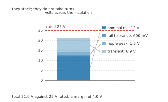
They stack. They do not take turns.
Worked example — Adding up what the insulation actually sees
The rail is nominally 12 V, held to 5.0 %, so it may sit 600 mV high before anything else happens.
On top of that the supply's ripple contributes 1.5 V at its peak, and the worst transient the circuit is expected to see adds 6.9 V.
Together the insulation is exposed to 21.0 V. Against a 25 V part that leaves 4.0 V of margin, which is 84.0 % of the rating in use. Judged on the nominal rail alone the same part looks like it is running at 48.0 %, and that is the number most people quote.
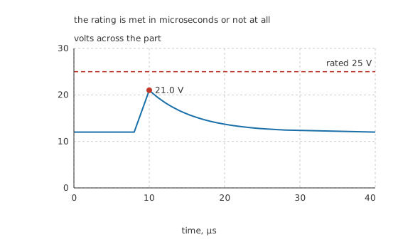
The rating is met in microseconds or not at all. Duration buys nothing.
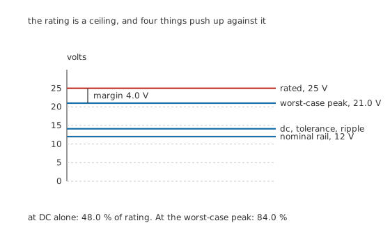
One volts-per-pixel scale through zero, so the gaps are the gaps.
The practical habit that comes out of this is a working ratio rather than a working voltage. Choose the part so that the worst-case peak, not the nominal rail, sits at a comfortable fraction of the rating. How comfortable depends entirely on the family, and the ranges are wide: film parts tolerate running near their rating, electrolytics prefer real headroom, tantalum parts want a great deal of it, and class 2 ceramics lose capacitance as the applied voltage rises whether or not they are anywhere near their rating.
Engineer
Where the rating comes from, and where it goes wrong
It is a property of the dielectric and its thickness
The dielectric has a breakdown field: volts per metre it can hold before it conducts. Multiply that by the thickness of the layer and you have the voltage the part can hold off. That is the whole of it, and it explains the shape of every family's catalogue. Dielectrics covers the material side.
It also explains why capacitance and voltage rating trade directly against each other in one package. Capacitance rises as the gap shrinks and the rating falls at exactly the same time, so within a given case size and dielectric, the higher-voltage part in the range holds less. A designer asking for more of both in the same footprint is asking for a better dielectric, not a better part number.
Two in series do not share as you would expect
Two 22 µF parts in series give 11 µF, and the obvious expectation is that they split an applied voltage evenly. At DC they do not, and the reason is that at DC a capacitor is not a capacitor at all. It is a very large resistance, its own leakage, and the string behaves as a resistive divider.
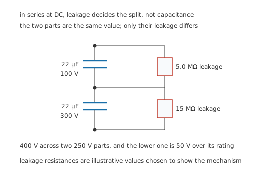
The two parts are the same value. Only their leakage differs, and the leakage is what decides.
Give one part 5.0 MΩ of leakage and the other 15 MΩ, put 400 V across the pair, and the split is 100 V to 300 V. Both parts are rated 250 V, so one of them is 50 V beyond its rating, in a circuit that a schematic review would pass. Leakage varies between nominally identical parts by more than this, and it drifts with temperature and age, so the split is not even stable.
Balancing resistors take the decision away
The fix is to put a resistor across each capacitor that is far stiffer than either leakage, so the leakage stops mattering. A 220 kΩ resistor across each part in the pair above pulls the split to 197.15 V and 202.85 V, both comfortably inside 250 V.
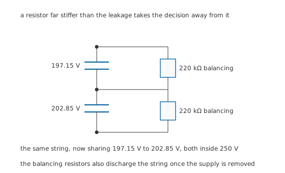
A resistor far stiffer than the leakage takes the decision away from it.
The resistors cost standing current and dissipation, which is the price of the arrangement, and they do a second job worth having: once the supply is removed they discharge the string, so the assembly does not sit at hundreds of volts waiting for somebody's hand. Testing capacitors treats that habit properly.
The same argument does not apply to fast transients. On a rising edge the string does divide by capacitance, because at those speeds the leakage is irrelevant, so a series pair can share well on a surge and badly at DC in the same circuit. Both cases have to be checked, and they have different answers.
Professional
AC, temperature, and what the rating stops promising
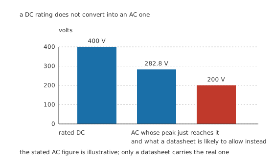
A DC rating does not convert into an AC one, and the shortfall is larger than the square root of two.
A part rated 400 V DC does not tolerate 400 V RMS of alternating voltage. The first reason is arithmetic: an RMS voltage of 282.8 V already reaches a peak of 400 V, so that is the ceiling before anything physical is considered. The second reason is that continuous alternating voltage drives current through the part every cycle, and that current heats it from the inside in a way a static DC voltage never does. So the stated AC rating comes out lower again. An illustrative figure of 200 V for that part sits 50.0 % below its DC rating, and only the datasheet for a specific part carries the real one.
Frequency matters as well as amplitude, because the current a capacitor passes rises with frequency. A rating quoted at mains frequency does not survive being applied at tens of kilohertz, which is why parts intended for switching converters carry a separate ripple-current specification rather than only a voltage. That specification, and the heat behind it, is what ESR is about.
Three more things the rating quietly stops promising.
Temperature. Most families derate their voltage above a stated temperature, sometimes steeply. A part comfortably inside its rating at room temperature can be outside it in an enclosure that runs forty degrees warmer, without a single circuit value changing.
Life at the rating. For an aluminium electrolytic, running near the rated voltage while hot is one of the two things that consume its life, the other being ripple current. The part does not fail at the rating; it ages faster there, and it fails earlier than the design expected. Failure modes and ageing follows that through.
Reverse voltage. On a polarised part, the rating is one-way. A few tenths of a volt the wrong way is tolerated on most electrolytics and effectively none is tolerated on a tantalum. Reverse voltage is not a small negative number on the same scale as the rating; it is a different failure mechanism with its own much smaller limit.
The one place where the rating genuinely is a design value rather than a limit is a safety capacitor across the mains, where the whole point of the classification is what happens when the part is destroyed. That is a different discipline and it gets its own lesson in X and Y safety capacitors.
Common mistakes
- Comparing the rating against the nominal rail — the rail's tolerance, its ripple and its transients all arrive at once. Compare the rating against the worst-case peak, which is a different and larger number.
- Assuming a series pair splits voltage evenly — at DC the split is set by leakage, not capacitance, and leakage varies widely between identical parts. Without balancing resistors one part can sit well over its rating.
- Treating a DC rating as an AC rating — an RMS voltage reaches a peak of √2 times itself before any heating is considered, and the stated AC figure is usually lower again.
- Ignoring temperature derating — a rating valid at room temperature can be reduced substantially in a warm enclosure, and nothing in the circuit has to change for the part to end up outside it.
- Treating a brief transient as harmless because it is brief — insulation breaks down on the field it sees, not on how long it sees it. Microseconds are long enough.
Frequently asked questions
How much should I derate a capacitor's voltage?
It depends on the family, and the sensible ranges differ by more than a factor of two between them. Film parts tolerate running fairly close to their rating, aluminium electrolytics want real headroom, and tantalum parts want a great deal of it. The rule that transfers is to derate against the worst-case peak the part will see rather than against the nominal supply.
What happens if a capacitor exceeds its voltage rating?
The dielectric breaks down and the part becomes a short across whatever was charging it, releasing its stored energy into that short. Some parts self-heal and carry on with slightly less capacitance, some fail open, and some fail closed and stay that way. Which of those happens is a property of the family rather than of the overvoltage.
Can I put two capacitors in series to double the voltage rating?
Only with balancing resistors across each. Without them the DC split is decided by the parts' leakage rather than their capacitance, and one of them can end up carrying most of the applied voltage while the other carries almost none.
Why is the AC voltage rating so much lower than the DC one?
Two reasons stack. An alternating voltage peaks at √2 times its RMS value, so the arithmetic ceiling is already well below the DC figure. On top of that, alternating voltage drives current through the part continuously and heats it from the inside, which a static DC voltage does not.
Does the voltage rating change with temperature?
For most families, yes, above a stated temperature. The derating curve is in the datasheet and it can be steep. A part inside its rating on a bench can be outside it in a warm enclosure with no circuit change at all.