
Quick Answer
A dielectric is the insulating material between a capacitor's plates. Its relative permittivity multiplies the capacitance the geometry alone would give, and its breakdown strength sets the voltage rating. Choosing a dielectric decides a capacitor's stability, losses and size far more than its marked value does.
Intuition
A field full of weathervanes
An insulator has no free electrons to carry a current, which is what makes it an insulator. Its charges are not motionless, though. They are tethered, and a tethered charge can still shift a little way, or swivel on the spot.
Picture a field of weathervanes on a still day, all pointing at random. Now a steady wind gets up, and every one of them swings round to face the same way. Nothing has travelled anywhere. The vanes are exactly where they were. But the field of them has acquired a direction it did not have before, and that direction pushes back against the wind.
That is a dielectric in an electric field. Its molecules stretch slightly, or rotate to line up, and the alignment sets up a small field of its own pointing back against the applied one. The two partly cancel, so the voltage across the material for a given amount of stored charge comes out lower than it would across empty space. Lower voltage for the same charge is exactly what more capacitance means.
Different materials swivel by different amounts, and the difference is not small. Air barely does anything at all. A plastic film manages a factor of two or three. Some ceramics manage a factor of several thousand, and that is the reason a modern surface-mount capacitor the size of a grain of rice can do a job that would once have needed a component the size of a thumb.
Practitioner
Relative permittivity, and what it buys
Every dielectric is quoted by its relative permittivity, written ε_r: the factor by which it multiplies the capacitance compared with the same electrodes in a vacuum. Vacuum is 1 by definition, and dry air is so close to 1 that the difference rarely matters. The plate formula carries the factor directly:
Worked example — One geometry, three materials
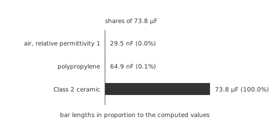
Take a rolled foil pair with 0.02 m² of facing area and a separation of 6.0 µm, and hold that geometry fixed while the material between changes.
With air, at 1.0, the pair comes to 29.5 nF.
With polypropylene film, whose relative permittivity is about 2.2, the same electrodes give 64.9 nF.
With a Class 2 ceramic formulation in the low thousands — take 2500 as a round illustration — the same geometry would give 73.8 µF.
Not one plate has moved. The entire difference, three and a half orders of magnitude of it, comes from what sits in the gap. (ε₀ throughout is 8.854 pF/m.)
Permittivity is only the headline, and the rest of the material's behaviour is what actually decides a design. A dielectric that gives a large value but shifts with temperature is fine across a supply rail and useless in a filter. One that loses capacitance under applied voltage is fine in a coupling path and a hazard in a timing circuit.
The families divide roughly by what they are made of. Plastic films — polypropylene, polyester, polycarbonate — are stable, low-loss and physically bulky. Class 1 ceramics such as C0G and NP0 use paraelectric formulations of modest permittivity, and are the stable ceramic choice. Class 2 ceramics such as X7R, X5R and Y5V use ferroelectric barium-titanate compositions of enormous permittivity, and pay for it in every kind of stability. Electrolytics grow a dielectric oxide film only nanometres thick on a roughened metal surface, buying capacitance from a tiny separation and a huge effective area rather than from permittivity. The ceramic, film and electrolytic lessons treat each family properly.
Picking one starts by asking what the value has to do rather than what it has to be. Bulk storage wants density and tolerates drift. Timing and filtering want a value that stays put. High-frequency decoupling wants low losses and low series inductance. Those three questions pick three different families, and they pick them before the capacitance is even chosen.
Engineer
Polarisation, and the field the material has to stand in
Alignment inside the material is called polarisation, and it has more than one mechanism. Electronic polarisation is the electron cloud of each atom shifting slightly against its nucleus, and it is quick enough to follow optical frequencies. Ionic polarisation is the ions of a lattice displacing against each other, and it fades out in the infrared. Dipolar polarisation is whole polar molecules rotating to line up, and it is slow — slow enough that it falls away across the radio spectrum, taking part of the permittivity with it as frequency rises.
This is why a dielectric constant is only meaningful with a frequency attached. A material quoted at 1 kHz may behave quite differently at 100 MHz, because one of its polarisation mechanisms has stopped keeping up. Each mechanism also dissipates energy as it lags behind the field, which is where dielectric loss comes from, and the loss peaks near the frequency where the mechanism is giving up.
The same reasoning sets the failure limit. Polarisation is a tethered displacement, and the tether has a breaking strain. Push the field high enough and charges tear free, the material conducts, and the capacitor is destroyed. That threshold is the material's dielectric strength, quoted as a field rather than a voltage:
Worked example — The field inside a film capacitor
Put 400 V across the polypropylene pair from Layer 2, whose film is 6.0 µm thick. The field in the dielectric is 66.7 MV/m.
Dry air at sea level breaks down in a uniform gap at roughly 3.0 MV/m. The film is therefore standing in a field about 22.2 times what air can tolerate, and doing it without complaint.
A solid dielectric exists to win exactly that ratio. It also explains why a void inside one is so dangerous: a gas-filled cavity in the film sees a comparable field, cannot stand it, and ionises. The resulting partial discharge erodes the surrounding material a little more with every cycle.
Thin is therefore not a free win. Halving the thickness doubles the capacitance and doubles the field at the same voltage, so the voltage rating halves. Every capacitor family sits at some chosen point on that trade, and the choice is why two parts of identical capacitance and wildly different physical size are both honest products.
The picture also has a limit worth stating plainly. Relative permittivity is treated here as a single number multiplying a geometry, which is a linear, lossless, frequency-independent model. Real dielectrics are none of those things: their permittivity is complex, frequency-dependent, and in Class 2 ceramics it depends on the applied field as well. The single number is a working approximation that holds well for film and Class 1 ceramic over ordinary conditions, and holds badly for Class 2 ceramic anywhere near its ratings.
Professional
The properties nobody puts on the label
The marked value tells you almost nothing about the four things most likely to cost you a design cycle.
Loss is quoted as a dissipation factor, the tangent of the angle by which current leads voltage short of a perfect quarter cycle. It behaves as an equivalent series resistance, it rises with frequency and with temperature, and it turns ripple current into heat inside the part. A polypropylene film capacitor's dissipation factor is a small fraction of a Class 2 ceramic's, which is why the film part survives in a switching supply's snubber where the ceramic cooks.
Leakage is never zero, because no insulator is perfect. Datasheets express it either as a leakage current at rated voltage or as an insulation resistance, and a self-discharge time constant follows straight from the second of those:
Worked example — How long the charge stays put
Suppose the polypropylene part is quoted at an insulation resistance of 100 GΩ — an illustrative figure, not a catalogue value, since real quotes vary by family and by temperature.
Against its 64.9 nF of capacitance that gives a self-discharge time constant of 6493 s, which is a couple of hours. The part is effectively still charged long after everything around it has stopped.
Scale that thought up to a supply reservoir and it stops being a curiosity: a large capacitor in a mains-derived rail can hold a dangerous voltage for a long time after power-off, which is why bleeder resistors exist and why charging and discharging takes the practice seriously. Leakage rises steeply with temperature in electrolytics, and it is the mechanism behind the "capacitor holds charge until you turn your back" experience.
Dielectric absorption is subtler and catches people out. Some materials retain a fraction of their polarisation after a fast discharge and then relax it back, so a capacitor shorted for a moment and released climbs back to a few per cent of its original voltage. Polypropylene and polystyrene are the good materials here, electrolytics and Class 2 ceramics the poor ones, and the effect ruins sample-and-hold and integrator accuracy long before it does anything else.
Ferroelectric formulations bring their own signature: they are piezoelectric, so a Class 2 ceramic capacitor mechanically deforms with applied voltage. On a board carrying an audio-frequency ripple that deformation drives the PCB as a diaphragm, and the result is the audible whine sometimes heard from switching supplies. It runs the other way too, so a flexed board or a nearby impact injects a voltage into a sensitive node.
Choosing well, then, is a materials decision dressed up as an electrical one. Ask what has to stay constant, what the losses are allowed to be, and what the part will be asked to survive; the family follows from those answers, and the capacitance is the easy part to fix afterwards.
Common mistakes
- Quoting a dielectric constant without a frequency — polarisation mechanisms drop out as frequency rises, so a material's permittivity at 1 kHz can be well above its value in the radio range.
- Substituting a Class 2 ceramic for a Class 1 part of the same value — the marked capacitance matches, and the temperature coefficient, bias behaviour and absorption do not.
- Treating dielectric strength as a voltage — it is a field, so the rating depends on the thickness of the material, not on the material alone.
- Assuming a thinner dielectric is a straight win — the capacitance rises and the voltage rating falls with the same factor.
- Ignoring dielectric absorption in precision analogue — a discharged capacitor that climbs back to a per cent or so of its old voltage will quietly ruin a sample-and-hold.
- Forgetting that a capacitor stays charged — leakage sets a self-discharge time constant that can run to hours in a good part.
Frequently asked questions
What does a dielectric do in a capacitor?
It insulates the plates from each other and polarises in the applied field, partly cancelling that field. The result is more stored charge per volt, so the capacitance is multiplied by the material's relative permittivity.
What is relative permittivity?
The factor by which a material multiplies the capacitance of a given pair of electrodes compared with a vacuum. Vacuum is exactly 1, dry air is very close to it, plastic films sit near 2 to 3, and Class 2 ceramics reach into the thousands.
Why does capacitance change with frequency?
Permittivity comes from several polarisation mechanisms, and the slower ones stop following the field as frequency rises. Each one that drops out takes part of the permittivity with it, and dissipates energy on its way out.
What is dielectric strength?
The electric field a material withstands before it breaks down and conducts. It is a field, in volts per metre, so the voltage a part survives depends on how thick its dielectric is.
Which dielectric should I choose for a timing circuit?
A stable one: Class 1 ceramic such as C0G or NP0, or a polypropylene or polystyrene film. Class 2 ceramics and electrolytics move too much with temperature, voltage and age to set a time interval.
Knowledge check
A capacitor's air gap is replaced by a film of relative permittivity 3, with the plates untouched. What happens to the capacitance? (Show answer)
What field does 50 V produce across a dielectric layer 2 µm thick? (Show answer)
Why do Class 2 ceramics give so much more capacitance than film for the same size? (Show answer)
A capacitor is shorted briefly, then left open, and its voltage creeps back up. What is happening? (Show answer)
Why does halving the dielectric thickness not simply double a capacitor's usefulness? (Show answer)
References
- CRC Press, CRC Handbook of Chemistry and Physics — dielectric constants of solids and the conventional breakdown field of dry air at sea level.
- CODATA / NIST, Fundamental Physical Constants — the electric constant ε₀ used in the worked examples.