
Quick Answer
A coupling capacitor sits in series between two stages so the signal passes and the DC does not. Each stage keeps its own operating point. The capacitor and the load resistance form a high-pass filter, so the value is chosen to put that corner well below the lowest frequency that matters.
Intuition
A letterbox in a front door
A letterbox is a hole in a door that lets one thing through and not another. Letters go in; the draught, mostly, does not. It works because it is sized and shaped for the thing it should pass, and the thing it should stop is a different kind of thing rather than a smaller one.
A coupling capacitor is that hole. Two stages of a circuit each need their own steady operating voltage: a transistor stage might sit at 6.0 V at its output while the stage after it wants its input at 1.5 V. Connect them directly and one of them is wrong. Connect them through a capacitor and the difference simply appears across the capacitor, permanently, while the changes pass straight through.
That is what "coupling" means here, and the second name for the same part, "DC blocking capacitor", says the other half. It is one of the most common uses of a capacitor in the world, and the whole of its design comes down to one question: how low a frequency does the signal go, and what is the capacitor allowed to do to it there?
Because a capacitor's reactance rises as the frequency falls, the arrangement always attenuates something. There is no value that passes everything, and picking a value is picking where the damage starts.
Practitioner
Where the corner goes, and what it costs
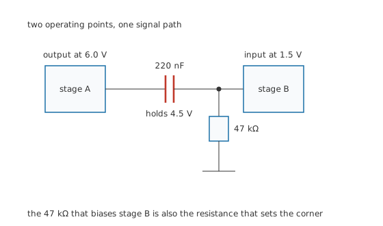
The resistor that biases stage B is also the resistance that sets the corner.
The capacitor is not on its own. Whatever resistance sits on the far side of it, usually the following stage's input resistance or its bias network, makes a high-pass filter with it.
Worked example — What 220 nF into 47 kΩ actually passes
The pair puts the corner at 15.39 Hz, where the output is down three decibels.
At 20 Hz, the bottom of what most people can hear, the response is 0.792 of the input, which is -2.02 dB. That is audible on a system anybody cares about and inaudible on most.
At 100 Hz it is 0.988, or -0.102 dB, which is nothing at all.
The capacitor also holds the DC difference between the two stages: 6.0 V on one side, 1.5 V on the other, 4.5 V across it forever.
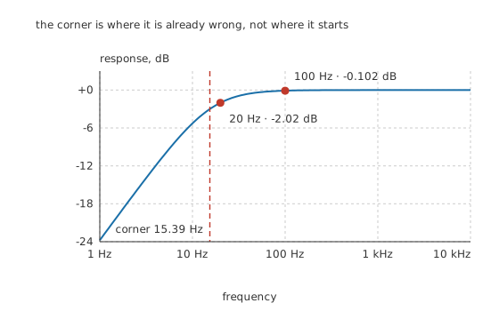
The corner is where it is already wrong, not where it starts.
The design rule that falls out of this is that the corner belongs somewhere below the passband rather than at its edge. A corner placed exactly at the lowest wanted frequency costs three decibels there, which is a lot. Placing it a factor of three or so lower brings the loss down to a fraction of a decibel, and the price is a larger capacitor.
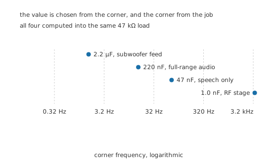
One decade of capacitance moves the corner one decade the other way.
Engineer
The corner is not a property of the capacitor
The single most useful thing to understand about coupling is that the same capacitor gives different corners in different circuits, because the resistance is half of the pair.
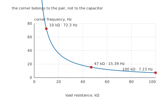
The corner belongs to the pair, not to the capacitor.
Drop the load to 10 kΩ and the corner climbs to 72.3 Hz, which would take a visible bite out of the bass. Raise it to 100 kΩ and it falls to 7.23 Hz. Nothing about the capacitor changed.
Two practical consequences. First, a coupling capacitor copied from one design into another can be wrong by a decade without anybody changing its value. Second, the resistance that matters is the total: the following stage's input resistance in parallel with any bias network, plus the driving stage's output resistance in series. On a high-impedance node the load dominates; on a low-impedance one the source can.
The same thing seen in time
A high-pass corner and an RC time constant are the same fact stated twice. The corner at 15.39 Hz corresponds to a time constant of 10.34 ms, and a square wave shows it directly.
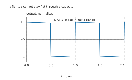
A flat top cannot stay flat through a capacitor.
A 1.0 kHz square wave has a period of 1.0 ms, so each half-cycle lasts half of that, and in that time the output droops 4.72 % toward zero. Small, and visible on a scope. Feed the same circuit a 50 Hz square wave, with its 20 ms period, and the sag is 62.0 %: the output no longer resembles a square wave at all.
That is why a coupling capacitor chosen by ear for audio can be badly wrong for a digital or pulse signal. Sag is the time-domain name for exactly the low-frequency loss the response curve shows, and a signal with a DC-like flat section is mostly low frequency. The high-pass filter works the frequency-domain half of this properly.
Professional
What a chain of them does, and which part to use
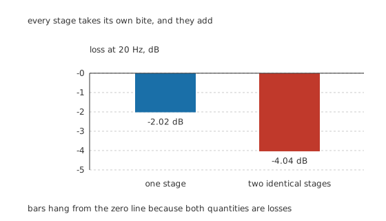
Every stage takes its own bite, and they add.
Decibels add along a signal chain. One coupling stage costing -2.02 dB at 20 Hz is a defensible choice; two identical ones cost -4.04 dB, a voltage ratio of 0.628 rather than 0.792, and a five-stage amplifier built from individually acceptable choices is not acceptable at all.
The habit that follows is to design the chain rather than the stage. Either put every corner far enough down that their sum is small, or deliberately give one stage the corner and make the rest an order of magnitude below it, so the response has one identifiable knee rather than a soft slump nobody can attribute.
Which family to use, and why it matters more here than elsewhere
A coupling capacitor carries the signal itself, so its own imperfections land directly in the signal path. That makes this one of the few positions where the dielectric choice is audible rather than academic.
Class 2 ceramic is the poor choice, and for a reason beyond its capacitance loss under bias. A ferroelectric dielectric's capacitance changes with the instantaneous voltage across it, so a signal large enough to swing that voltage modulates the value at signal rate, and modulation of a filter by its own signal is distortion. A part that has lost most of its value to bias is also, by that point, a much higher corner than the design assumed.
Class 1 ceramic and film are the good choices. Both hold their value against bias, and film adds very low dielectric absorption, which matters where the signal has a DC-like component that keeps the capacitor at one polarity for a long time.
Electrolytics are used, and they need care. At the values a low corner into a high impedance demands, film becomes physically large and an electrolytic is the practical answer. The difficulty is that they are polarised and a coupling position may see either polarity. The usual answers are to ensure a DC bias always keeps the part correctly polarised by a comfortable margin, or to use a non-polarised type built as two parts back to back.
The current that is not signal
One quiet failure mode deserves naming. If the stage on the far side draws a DC input current, that current has to come through the capacitor, and it cannot: a capacitor passes no steady current. What actually happens is that the input current flows in the bias network instead, and any leakage through the capacitor adds to it. On a high-impedance node with a leaky capacitor, that leakage develops a voltage across the bias resistance and shifts the following stage's operating point, sometimes far enough to stop it working.
A part with rising leakage, which is what an ageing electrolytic is, therefore presents as a slowly drifting bias rather than as a frequency-response problem. Testing capacitors covers measuring leakage, and choosing the right capacitor puts the family choice beside the value.
Common mistakes
- Putting the corner at the lowest wanted frequency — the corner is three decibels down. It belongs a factor of three or more below the passband, not at its edge.
- Copying a coupling value between designs — the corner depends on the resistance as much as the capacitance, and a different input impedance moves it by whatever factor it differs by.
- Forgetting that corners add along a chain — several stages each individually acceptable can be unacceptable together, because the decibels sum.
- Using a class 2 ceramic in a signal path — its capacitance varies with the instantaneous voltage across it, which modulates the filter with the signal and produces distortion on top of the bias loss.
- Treating sag and low-frequency roll-off as different problems — they are the same time constant seen in two domains, and a pulse signal is mostly low frequency.
Frequently asked questions
What does a coupling capacitor do?
It passes changing signals between two stages while blocking the steady voltage difference between them. That lets each stage sit at whatever operating point it needs without the other one interfering, and the DC difference simply appears across the capacitor.
How do I choose the value of a coupling capacitor?
Work backwards from the lowest frequency that matters. Put the corner a factor of three or more below it, then compute the capacitance from that corner and the resistance the capacitor works into, which is the following stage's input resistance in parallel with its bias network.
Why does my square wave droop after a coupling capacitor?
Because a flat top is a low-frequency component, and the coupling capacitor attenuates low frequencies. The droop is the same time constant that sets the corner, seen in the time domain: over each half-cycle the output decays toward zero by an amount set by the ratio of that half-cycle to the time constant.
Can I use a ceramic capacitor for coupling?
A class 1 ceramic, yes, and it is a very good choice. A class 2 ceramic is a poor one: its capacitance falls under bias and also changes with the instantaneous signal voltage, which modulates the filter with the signal and produces distortion.
Which way round does an electrolytic coupling capacitor go?
With its positive terminal on whichever side has the higher DC voltage, and that must be true under every operating condition rather than most of them. Where the polarity could reverse, a non-polarised type or a film capacitor is the answer, because even brief reverse voltage damages a polarised part.