
Quick Answer
A single-phase induction motor produces no starting torque on its own. A capacitor in series with a second winding shifts that winding's current in time, giving a rotating field. Run capacitors are energised continuously and sized for an angle; start capacitors are much larger and connected only for seconds.
Safety
Everything in this lesson sits directly on the mains. A motor capacitor is connected between live conductors, and when the supply is removed it can hold a charge at the peak of the cycle for a long time: the figures below show over four hours to fall to a safe level without a bleed resistor. Never assume a motor capacitor is discharged because the machine is unplugged, and never open a motor terminal box on the assumption that switching off is enough. Every number here is arithmetic on illustrative component values rather than a measurement of a machine, and none of it is a procedure for working on a live appliance.
Intuition
Two people pushing a roundabout
A playground roundabout is easy to keep moving and hard to start. One person pushing it can get it going by walking round with it, but two people pushing in perfect unison from opposite sides achieve nothing at all: their forces cancel and the thing sits there. What starts it is two people pushing out of step, one leading the other, so there is always a push arriving at a place the roundabout has not reached yet.
That is exactly the problem a single-phase induction motor has. Its winding produces a magnetic field that grows, collapses and reverses along one axis, and a field like that has no preferred direction of rotation. Once the rotor is turning it will keep it turning, in whichever direction it happens to be going. From standstill it produces no starting torque whatsoever, and the motor sits and hums.
The fix is a second winding, physically placed at an angle to the first, carrying a current that is out of step in time. Two forces, offset in space and offset in time, add up to a field that sweeps round rather than pulsing in place, and a sweeping field drags the rotor with it.
Getting a current out of step is what the capacitor is for. Put one in series with the second winding and that winding's current leads instead of lagging, and the two together become the two people pushing out of step. Nothing else in a single-phase supply will do it as cheaply.
Practitioner
Sizing the capacitor for an angle
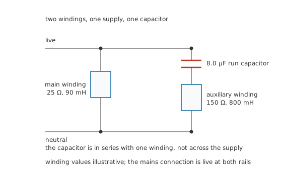
The capacitor is in series with one winding, not across the supply.
The auxiliary winding on its own is an inductance, so its current lags. Put enough capacitive reactance in series and the branch becomes net capacitive, and the current leads instead. The size of the capacitor decides by how much.
Worked example — What an 8.0 µF run capacitor achieves
On a 230 V supply at 50 Hz, an illustrative main winding of 25 Ω and 90 mH has a reactance of 28.27 Ω, an impedance of 37.74 Ω, and draws 6.094 A lagging by 48.52°.
The auxiliary winding is 150 Ω and 800 mH, so 251.3 Ω of inductive reactance. A 8.0 µF capacitor contributes 397.9 Ω the other way, which is more than enough to reverse the sign. The branch impedance is 209.7 Ω, it draws 1.097 A, and its current now leads by 44.34°.
The two are 92.85° apart. That is the whole design objective, and it is why the value is chosen rather than maximised.
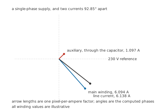
Arrow lengths are one pixel-per-ampere factor; the angles are the computed phases.
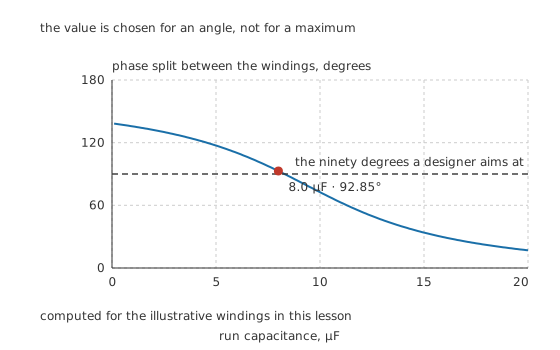
The value is chosen for an angle, not for a maximum.
Because the two branch currents are nearly a quarter cycle apart, they do not add arithmetically.
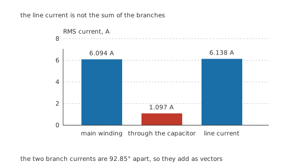
The line current is not the sum of the branches, because they are 92.85° apart.
The line current comes to 6.138 A lagging by 38.24°, which is a power factor of 0.785.
The supply therefore delivers 1.4117 kVA of apparent power, of which 1.1089 kW is real and 873.8 var is reactive. AC power sets out what that split means; the point here is that the capacitor improves the power factor as a side effect while it does its real job of splitting the phase.
Engineer
Two capacitors, two completely different jobs
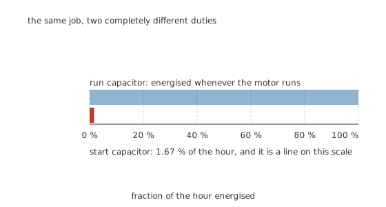
The same job, two completely different duties.
A run capacitor stays connected whenever the motor runs. It is sized for the phase angle at the running condition, and it carries alternating current continuously, so its whole specification is about surviving continuous AC duty: a modest capacitance, a substantial AC voltage rating, and metallised polypropylene film construction because film tolerates continuous alternating voltage without heating itself to death.
A start capacitor is a different component doing a different job. It is much larger, because at standstill the winding impedances are different and a bigger phase shift is wanted for torque. A 100 µF part has a reactance of only 31.83 Ω at 50 Hz, so it passes a large current, and it is switched out by a centrifugal switch or a relay once the motor is up to speed.
That switch is what makes the duty possible. Carrying 3.0 s per start, 20 times in 3.6 ks, the part is energised for 1.67 % of the hour. That is why a start capacitor can be a small, cheap electrolytic built for AC service, rated in a way that would destroy it in minutes on continuous duty.
The failure mode that follows is the classic one. If the switch does not open, the start capacitor stays in circuit at a hundred percent duty and fails, usually quickly and sometimes messily. A motor that hums, draws heavy current and does not start is the same symptom read the other way: either the capacitor has failed or the switch has not closed, and the winding is being asked to start on one phase.
Why the values are not interchangeable
Fitting a larger run capacitor does not give more torque; it moves the phase split toward ninety degrees and then past it into undershoot, as the curve above shows, and it increases the current in a winding sized for less. Fitting a smaller one overshoots. Fitting a start capacitor permanently overloads it. The value on the side of the old part is the specification, and the substitution rule for these is unusually strict.
The one substitution that is often acceptable is a higher voltage rating at the same capacitance, because the voltage rating on these parts is an AC rating with real headroom built in. Voltage ratings and derating explains why an AC rating is not the DC one and why the two must not be swapped.
Professional
The charge it holds when the machine is off
A capacitor across the mains is disconnected at some arbitrary point in the cycle, and the worst case is the peak.
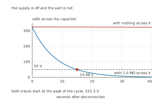
The supply is off and the part is not. Both traces start at 325.3 V.
A 230 V supply peaks at 325.3 V, and that is where the capacitor can be left. With a 1.0 MΩ bleed resistor across it, the time constant is 8.0 s and the voltage falls below 50 V after 14.98 s. With nothing across it but an illustrative 1.0 GΩ of its own leakage, the time constant is 8.0 ks and the same fall takes 14.98 ks, which is over four hours.
Four hours is long enough that the appliance has been carried to a bench, opened and worked on. This is the single most important practical fact in the lesson, and it is why bleed resistors are fitted, why they are checked, and why testing capacitors treats proving a part dead as a procedure with a measurement in it rather than an assumption.
What fails, and what it looks like
The capacitor loses capacitance. Metallised film clears its own faults, and each clearing costs a little of the plate. Over years of continuous AC duty in a warm motor housing, enough clearings accumulate that the value drifts down. The phase split moves off its design angle, torque falls, the motor runs hot and starts reluctantly. Nothing looks broken.
The capacitor fails open. Same symptoms, arrived at suddenly. A motor that used to start and now hums until its thermal cut-out opens is the standard presentation.
The case bulges or leaks. Overheating, over-voltage or simply age. Run capacitors sit inside or on top of a motor and see the motor's temperature, so their thermal environment is far worse than a bench measurement suggests.
The start switch sticks closed. The start capacitor then runs continuously and does not survive it. This is a motor fault presenting as a capacitor fault, and replacing the capacitor without checking the switch replaces it again shortly afterwards.
The measurement that separates them is a capacitance reading on a part that has been removed and proved dead, compared against the value printed on it. A part more than a few percent below its marking has aged out, whatever it looks like. Capacitor failure modes follows the mechanism in general, and choosing the right capacitor covers what a replacement has to match.
Common mistakes
- Assuming an unplugged motor's capacitor is discharged — without a working bleed resistor it can hold a dangerous voltage for hours. Prove it dead with a meter before touching a terminal.
- Fitting a larger run capacitor for more torque — the value is chosen for a phase angle, and going past that angle reduces torque while increasing winding current.
- Substituting a start capacitor for a run capacitor — a start capacitor is built for a duty of a few seconds an hour and will not survive continuous energisation.
- Replacing a failed start capacitor without checking the switch — a switch that fails to open leaves the start capacitor connected permanently, which is what destroyed the first one.
- Reading an AC voltage rating as if it were a DC one — motor capacitors are rated for continuous alternating voltage, and the two ratings are not interchangeable in either direction.
Frequently asked questions
Why does a single-phase motor need a capacitor to start?
Because a single winding produces a field that pulses along one axis rather than rotating, and a pulsing field exerts no starting torque. A second winding carrying a current out of step in time turns the pulsing field into a rotating one. The capacitor is what shifts that current in time.
What is the difference between a start capacitor and a run capacitor?
Duty and size. A run capacitor is small, connected whenever the motor runs, and sized for the phase angle at running speed. A start capacitor is much larger, connected only for the few seconds of starting, and switched out afterwards. Its rating assumes it is energised for a small fraction of each hour.
Can I fit a larger capacitor for more starting torque?
No. The value sets a phase angle, and there is a value that gives the best angle. Going above it moves the split toward ninety degrees and then past it into undershoot, so torque falls while the current in the auxiliary winding rises. The printed value is a specification, not a minimum.
How long does a motor capacitor stay charged after switch-off?
With a working bleed resistor, seconds. Without one, hours: a part with only its own leakage across it has a time constant of thousands of seconds, so it can still be at a dangerous voltage long after the appliance has been moved and opened. Always measure rather than assume.
How do I tell whether a motor capacitor has failed?
Remove it, prove it is discharged, and measure its capacitance against the value printed on the case. Metallised film capacitors lose capacitance gradually as they clear faults, so a part several percent low has aged out even though it looks perfect. A bulged or leaking case is a failure regardless of what it measures.