
Quick Answer
A motor turns because a current-carrying conductor in a magnetic field feels a force. A generator produces voltage because a conductor moving through a field has one induced in it. These are the same machine described from two sides, and any motor driven by its shaft will generate.
Intuition
One machine, read in either direction
Take a small DC motor with nothing connected to it, put a voltmeter across its terminals, and spin the shaft between your fingers. The meter reads a volt or so, and reverses when you spin it the other way. Connect a battery instead and the shaft turns. The same two wires, the same magnets, the same coil, and no modification of any kind between the two experiments.
That reversibility is not a coincidence of construction. A current in a field feels a force, which is what makes a motor; a conductor moving through a field has a voltage induced in it, which is what makes a generator; and any machine built to do one of those does the other whether you asked for it or not. A loudspeaker wired to a microphone input works as a microphone. A ceiling fan spun by the wind makes electricity.
The consequence that matters most in practice is that a motor is always generating while it runs, against the very supply driving it. That self-generated voltage is called the back-emf, it grows as the machine speeds up, and it turns out to be the thing that decides how much current a motor draws. Layer 3 works that through, and it is the single most useful piece of motor theory a designer can carry.
Practitioner
From force to turning force
A straight conductor lying across a magnetic field and carrying a current is pushed sideways, at right angles to both:
Arrange that conductor as one side of a loop, mounted so it can turn, and the opposite side carries the current back the other way. Since the current there runs the opposite direction, the force on it is opposite too — and two opposite forces on opposite sides of an axis are a torque.
Worked example — One loop between the poles
A conductor 60 mm long, carrying 3.0 A across a field of 450 mT, feels 81.0 mN.
With both sides of the loop acting on arms of 25 mm, the loop produces 4.05 mN·m of torque.
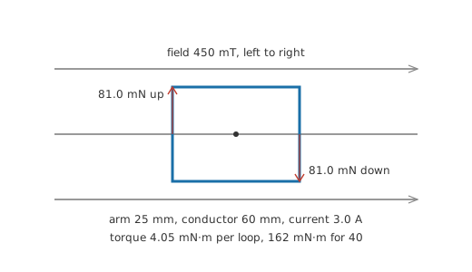
Four millinewton metres is not much, which is why real machines do not use one loop.
Worked example — A wound armature
Wind 40 such loops onto the same rotor and the torque becomes 162 mN·m, for the same field and the same current in each conductor.
The remaining difficulty is that a loop which has turned through half a revolution now has its sides the wrong way round, so the torque would reverse and the rotor would rock rather than spin. A commutator solves it mechanically, reversing the current in each loop as it passes the neutral point, so the torque always pushes the same way round. A brushless machine solves the same problem electronically, which is why it needs to know where the rotor is and why the Hall effect shows up inside one.
Torque is also not constant through a revolution, and the expression above quietly assumes the best case. A loop lying flat in the field has both its active sides pushing at right angles to the arm, which is where the full torque appears; a quarter turn later those forces point along the arm instead and produce none at all. A single-loop machine therefore delivers torque that swells and dies twice per revolution, and the standard remedy is many loops set at different angles so that some are always well placed. The torque an armature delivers is the sum over all of them, which is why the second worked example multiplies rather than something more elaborate, and why a real machine's torque ripple is a manufacturing figure rather than zero.
Two design levers are visible in the relationship, and both are used. Field strength is one, which is why the magnets in a small machine are the expensive part and why a wound-field machine can be controlled through its field winding. Conductor length in the field is the other, and it explains the shape of motors: a long thin machine has more conductor in the field per unit of rotor mass than a short fat one, so it produces more torque for its inertia, while a short fat one wins on peak torque for its length. Neither lever touches the current, which is set by the supply and the back-emf rather than by anything the designer of the magnetics chooses.
Engineer
Back-emf, and what actually limits the current
Once the armature is turning, its conductors are moving through the field, so a voltage is induced in them by electromagnetic induction. Lenz's law fixes its direction: it opposes the supply that is driving the machine. The armature circuit is therefore the supply, minus the back-emf, across the winding's own resistance.
Worked example — A 12 V motor at standstill
With 12 V applied and a winding resistance of 1.2 Ω, and no back-emf at all because nothing is moving, the current is 10.0 A.
Worked example — The same motor up to speed
Running with a back-emf of 10.5 V, only 1.25 A flows — a factor of 8.0 less.
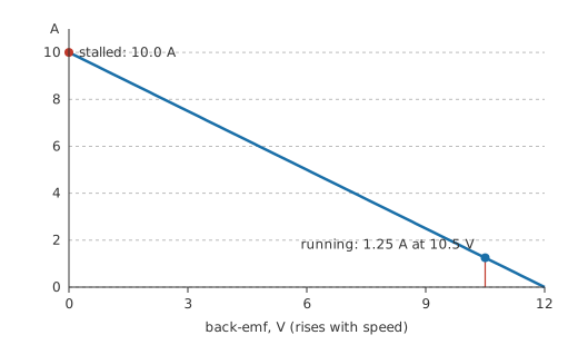
This is why a motor's stall current is enormous compared with its running current, why the lights dim when a fridge compressor starts, and why a motor that jams draws its stall current continuously and burns out. The winding is identical in both lines; what differs is whether the machine is generating against its own supply.
The power bookkeeping is where the physics becomes satisfying rather than merely useful.
Worked example — Where the supply's power goes
At the running point the supply delivers 15.0 W. The winding resistance turns 1.875 W of that into heat, and the back-emf accounts for 13.125 W.
Efficiency at this operating point is therefore 0.875.
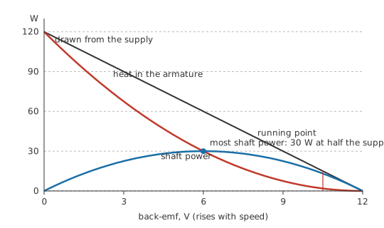
The back-emf term is not a loss; it is the shaft power, arriving in the equation as a voltage because that is how a generator appears to a circuit. Where the back-emf is zero, every watt goes into heat and none into motion, which is exactly the stalled case. Where the back-emf is high, little current flows and little power of any kind is converted. Maximum mechanical power sits halfway between, at a back-emf of half the supply, and the machine is only fifty per cent efficient there — the maximum power transfer theorem turning up in mechanical clothing, and the reason no motor is designed to run at its maximum-power point.
The model simplifies in two places worth naming. It treats the winding resistance as constant, and copper's resistance rises as it heats, so a hard-working motor draws somewhat less current than this predicts at the same speed. It also treats the field as fixed, which is true of a permanent-magnet machine and false of a wound-field one, where the field is itself produced by a current and the machine's whole speed-torque character changes with how that winding is connected.
Professional
Generating, braking, and what real machines add
Drive the shaft faster than the supply would, and the back-emf exceeds the supply. The current reverses, and the machine feeds power back.
Worked example — The same machine, driven
Turned fast enough to generate 15.75 V against the same 12 V supply, the machine pushes 3.125 A back into it, returning 37.5 W.
That is regenerative braking, and it is the same equation with one sign changed. An electric vehicle slowing down, a lift descending, a wind turbine in a gust: all of them are motors whose back-emf has overtaken their supply. The practical catch is that something has to accept the returned power. A battery will; a rectified mains supply generally will not, and the returned energy raises the DC bus voltage until either a braking resistor absorbs it or something fails.
Safety
Every figure above is paper arithmetic on a small 12 V machine, and none of it was measured on a bench. Two hazards scale with the machine rather than with the arithmetic. A rotating shaft stores real energy and does not care what is in the way of it, so guards, loose clothing and long hair are not optional around anything larger than a toy. And a machine that is coasting is a live generator: its terminals can carry a substantial voltage after the supply has been removed, which is why a motor is proved dead rather than assumed dead. Mains-fed and three-phase machines are licensed work in most jurisdictions, and electrical safety sets out the isolate-and-prove sequence that applies before anything is touched.
Real machines differ from the loop above in ways worth knowing before you choose one. A brushed DC motor is the direct realisation of Layer 2, cheap and easy to drive, with brushes that wear and spark. A brushless DC machine moves the commutation into electronics and the magnets onto the rotor, which removes the wear and adds a controller. An induction motor has no magnets and no connection to its rotor at all: the stator's rotating field induces currents in the rotor, and those currents produce the torque, which is why it must run slightly slower than the field and why it is the workhorse of industry. A stepper trades continuous rotation for countable positions.
Three things bite in practice regardless of type. Starting current is the stall current, so drives soft-start rather than switching straight on. Inductance means a motor is a coil, so switching its current abruptly produces the same flyback voltage any coil does, and a drive without a path for that energy destroys itself rather than the motor. And efficiency depends on the operating point, so a motor sized so it never leaves its efficient region will beat a larger one loafing or a smaller one straining.
The component-level treatment continues in DC motors, and the capacitors that single-phase machines need to start at all are covered in motor capacitors.
Common mistakes
- Sizing a supply for running current — a motor draws its stall current every time it starts, and continuously if it jams. The supply, the fuse and the driver all have to survive that.
- Thinking the back-emf is a loss — it is the shaft power, appearing as a voltage because a generator is what the moving armature has become. The loss is the winding resistance, and nothing else in the ideal model.
- Assuming a disconnected motor is dead — a coasting machine generates, and its terminals can be live long after the supply has gone.
- Switching a motor's current with no return path — the winding is a coil, and interrupting its current produces exactly the flyback voltage any coil would.
- Running at maximum power — that point is fifty per cent efficient by construction, so half the supply's energy becomes heat in the armature. Efficient operation is well above it, at high back-emf and modest current.
Frequently asked questions
Is a motor really the same thing as a generator?
Structurally, yes. The same machine converts electrical energy to mechanical or mechanical to electrical depending on which way power is flowing, and many machines routinely do both, such as an electric vehicle's traction motor under acceleration and under braking.
What is back-emf?
The voltage a motor generates as it turns, opposing the supply that drives it. It grows with speed, and the current a motor draws is set by the difference between the supply and the back-emf divided by the winding resistance.
Why does a motor draw so much current when it starts?
Because it is not yet turning, so there is no back-emf, and the only thing limiting the current is the winding resistance. Stall current can easily be ten times running current.
Why does a jammed motor burn out?
It sits at stall current indefinitely, which means all the supplied power goes into heating the winding, and the fan or airflow that would normally help cool it is not turning either.
What is regenerative braking?
Driving a motor's shaft faster than its own back-emf equilibrium so that current reverses and the machine returns power to the supply. It brakes the load and recovers some of the energy, provided the supply can accept it.
Why does an induction motor need no connection to its rotor?
Its rotor currents are induced by the stator's rotating field rather than fed in. That removes brushes and slip rings entirely, at the price of the rotor having to slip slightly behind the field for any current to be induced at all.