
Quick Answer
The maximum power transfer theorem states that a source with a fixed Thévenin equivalent delivers the most power to a load when the load resistance equals the source resistance. At that point the load receives the square of the source voltage divided by four times the source resistance, and efficiency is fifty per cent.
Intuition
The load that draws the most out of a source
A source is never quite the ideal thing its symbol suggests. Some resistance sits inside it, and that resistance has a say in how much power a load can draw out.
Take a source reading 6.0 V with nothing connected, behaving as though 3.0 Ω were in series inside it, and try different loads across its terminals.
A load of 1.0 Ω lets a lot of current through, 1.5 A, but holds only 1.5 V of the source's voltage — the rest is dropped across the resistance inside. Power is voltage times current, so this load receives 2.25 W.
At the other extreme, 9.0 Ω, the shortage moves to the current side. The load keeps 4.5 V, most of what there is, while only 0.5 A flows, and its power comes to 2.25 W, the same figure the small load reached from the other side.
Somewhere between the two sits 3.0 Ω, the value the source itself has. The current there is 1.0 A, the voltage is 3.0 V, and the load takes 3.0 W, more than either of the others.
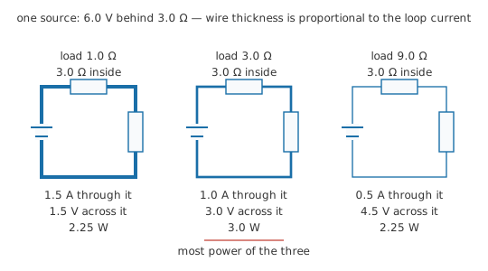
Push either extreme further and the load does worse still. Short the terminals and the current reaches its largest value, 2.0 A, with no voltage across the load and so no power in it. Leave the terminals open and the whole source voltage appears with no current at all, and again no power. Power falls away to zero at both ends of the range, so a best load exists somewhere inside it, and it turns out to be the one that matches the source.
Practitioner
Sizing the load against the source
Reduce whatever the source contains to its Thévenin equivalent — one voltage, one resistance — and the whole question becomes arithmetic on a single loop. The current is the equivalent voltage across the two resistances in series:
and the power the load receives follows from that current and its own resistance:
Set the load equal to the equivalent resistance and those two steps collapse into one expression built from the source's two numbers alone:
That result has a name of its own — the source's available power — and it is a ceiling: no load takes more, and the figure is a property of the source rather than of anything connected across it.
Worked example — A matched load and a badly chosen one
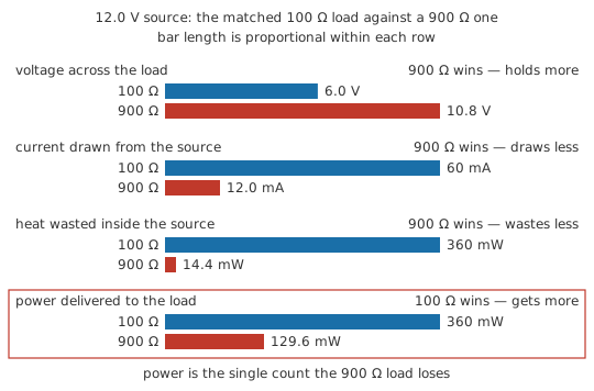
The source is 12.0 V behind 100 Ω. Matched, the load is 100 Ω, the loop carries 60 mA, the load holds 6.0 V — half the source voltage, as two equal resistances in series must give — and receives 360 mW. The closed form skips the intermediate steps and returns the same figure: 360 mW.
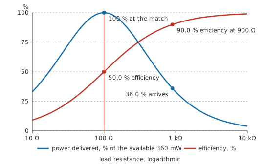
Now put 900 Ω across the same terminals — nine times too large, the kind of value you land on by choosing a load for the voltage it will read. Current falls to 12.0 mA, the load holds 10.8 V, almost everything the source has to offer, and takes 129.6 mW, which is 36.0 % of what was on the table.
All of this depends on knowing what feeds the terminals: its equivalent voltage and its equivalent resistance. Both come from the terminal measurements or the network reduction that produce a Thévenin equivalent in the first place, and a matched design is only as good as the resistance figure it was built on. Sources whose resistance moves with temperature, bias or frequency are matched at one operating point and mismatched elsewhere.
By almost any other measure the badly chosen load in that example did well: it read a higher voltage, drew less current and wasted less. Power was the single count it lost on, and that is the count that matters when power is what you came for.
Engineer
The load-power curve and its maximum
Write the load power as a function of the load resistance alone. The current in the loop is V_th ⁄ (R_th + R_L), so the power in the load is V_th² R_L ⁄ (R_th + R_L)². The two source figures are constants; R_L is the only variable, and the question is where that expression peaks.
Differentiating the load power with respect to the load resistance and setting the result to zero gives R_L = R_th. The quotient rule leaves a numerator proportional to (R_th − R_L): the R_L in the numerator pushes the power up, the squared sum in the denominator pulls it down, and the two rates of change cross at exactly one positive value of R_L, the one where the two resistances are equal. Either side of that crossing the derivative has a definite sign, so the stationary point is a maximum and there is no second one.
Minimising a denominator instead of differentiating
The same answer comes out without calculus, and this route produces the closed form along the way.
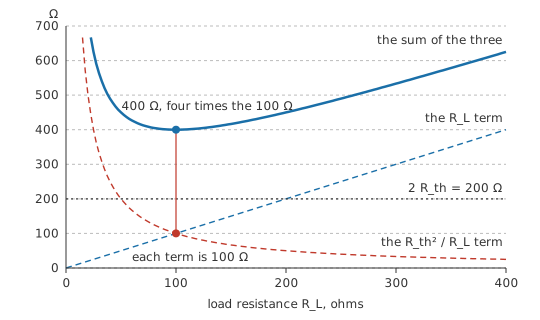
Divide numerator and denominator by R_L. The load power becomes V_th² divided by the quantity (R_th + R_L)² ⁄ R_L, so maximising the power means minimising that quantity. Expand it and it reads R_L + 2 R_th + R_th² ⁄ R_L. The middle term is a constant. The other two are a positive number and a fixed constant divided by that same number, and a sum of that shape is smallest when its two terms are equal, which happens at R_L = R_th, where each of them equals R_th and the whole quantity comes to four times the source resistance. Substitute that back:
The cost of getting the load wrong
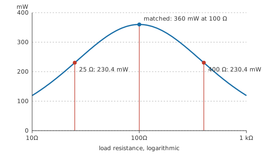
The peak is real, and it is also blunt, which matters more in practice than knowing exactly where it sits. Hold the source at 12.0 V behind 100 Ω and walk the load across a range of two decades:
- 25 Ω, a quarter of the source resistance: 230.4 mW, or 64.0 % of the peak
- 50 Ω, half of it: 320.0 mW, or 88.9 %
- 100 Ω, matched: 360 mW
- 200 Ω, twice: 320.0 mW, or 88.9 %
- 400 Ω, four times: 230.4 mW, or 64.0 %
Being wrong by a factor of two in either direction costs roughly a ninth of the available power, and a factor of four a little over a third. Closer in, a load of 110 Ω — ten per cent high — delivers 359.2 mW, which is 99.8 % of the peak, a loss no bench instrument in the signal path would resolve.
That table is symmetric under inversion: a load k times the source resistance and one k times smaller deliver identical power, which the two matching pairs above demonstrate. The flatness has a plain cause behind it. At a smooth maximum the first derivative is zero, so the leading term in the loss is quadratic in the mismatch. Halve the error and the shortfall drops by four.
The conditions the derivation used
A Thévenin equivalent exists only for a linear network, and the derivation worked entirely from that equivalent, so the network behind the terminals has to be linear. The source resistance has to hold still while the load is varied, since the whole of the calculus was performed with R_th treated as a constant, and what becomes of the conclusion once it does move is taken up at the end of this lesson. And the load has to be a resistance: pure reactance takes no average power at all, so the result stated here is a DC statement that needs generalising before it applies to an AC circuit.
The equivalence is a terminal one, as always. The equivalent reproduces what happens between the two terminals and keeps no account of the interior, so its figure for the load's power is exact, while the figure it appears to give for the source's own resistance belongs to the model alone.
Professional
The fifty per cent that never reaches the load
Half the power stays inside the source
At the matched point the two resistances are equal and carry one current, so each dissipates the same amount. The worked source hands its load 360 mW and turns 360 mW into heat inside itself, drawing 720 mW in total.
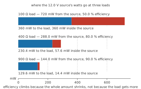
Efficiency there is 50.0 %, and no load improves power and efficiency together. Move up to 400 Ω and the source delivers 288.0 mW of which the load keeps 230.4 mW: 80.0 % efficiency for 64.0 % of the available power. At 900 Ω the totals are 144.0 mW supplied, 129.6 mW delivered, 90.0 % efficiency, 36.0 % of the peak. Efficiency climbs towards unity as the load grows while the power in it slides away.
Matching where the power is scarce
An antenna presents whatever source resistance its geometry gives it; a piezo element, a thermocouple, a small photovoltaic cell, a coil pickup and a thermoelectric harvester are in the same position. Half is an acceptable price when the available power is that small and there is no more of it to be had. Uncollected power is lost rather than stored: it is reflected, or it is never converted in the first place. Matching therefore buys the largest signal the source is capable of producing.
Radio-frequency work has a further reason for matching on top of that one: an unmatched termination sends part of the incident wave back along the line, and the returning energy is a problem in itself before anyone has counted watts. Impedance matching treats that case properly. The matched interfaces of older audio and telephone line practice share the same ancestry, and the line impedance there is a property of the cable.
Where matching is the wrong target
The theorem reports the top of one curve. Whether you want to sit at that top is a separate decision, and for anything whose job is to move energy — a mains distribution network, a bench supply, a battery pack, a regulator — half the energy converted to heat inside the source is a specification nobody would sign.
Those systems are built the other way round: source resistance pushed as low as the design allows, load far above it, so nearly all the voltage and nearly all the energy arrive where they were sent. A supply's output resistance is quoted in milliohms while the load it feeds is measured in ohms, and distribution conductors are sized for a drop of a few per cent. Each of those designs sits a long way from its own maximum-power point, and the distance is deliberate.
The assumption that the source resistance is fixed
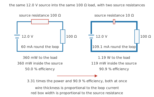
The theorem asks which load extracts the most from a source you are not allowed to change. Where the source resistance is yours to set, lowering it beats matching every time.
Feed the same 12.0 V source into a fixed 100 Ω load and reduce the source resistance to 10 Ω. Current rises to 109.1 mA, the load receives 1.19 W against the 360 mW the matched arrangement managed — a factor of 3.31 — while the total drawn is 1.31 W and efficiency stands at 90.9 %. Both figures improve at once, and they do so by moving the one quantity the theorem holds still.
Read as an instruction, the theorem also produces some alarming loads. A battery of 12.0 V with an internal resistance of 10 mΩ has its maximum-power point at a load equal to that resistance: 600 A through the pack, 3.6 kW in the load and the same again inside the cells, 7.2 kW altogether. The arithmetic behind those figures is correct, and a pack asked to work at that point is on its way to a fire.
Safety
The battery figures above came from a published internal resistance and a line of algebra. No cell was loaded to obtain them. Never load a cell, a pack or a mains-derived supply towards its maximum-power point: the current there is half the short-circuit current, which for lithium and lead-acid chemistries runs to hundreds of amperes — welded leads, vented cells, burns and fire. Characterise a source with a load that keeps the current well inside the manufacturer's rating, and fuse the measurement path.
Beyond DC, and back to the real network
With reactance in the circuit the same question is asked of impedance instead of resistance, and the answer generalises: the load that receives the most power is the complex conjugate of the source impedance — equal resistive part, opposite sign of reactance, so the two reactances cancel and the loop is left purely resistive at that frequency. That is the derivation above run with two variables instead of one. Its frequency-specific character is what turns broadband matching into a design problem of its own.
A caution follows from Thévenin's theorem. An equivalent resistance is the slope of a terminal characteristic, so the internal dissipation quoted above is a property of that slope. The heat itself is spread among whatever branches the real source contains, in proportions the equivalent never recorded. Component ratings and heatsinking therefore go back to the real circuit and the methods in power dissipation.
Common mistakes
- Reading the theorem as advice. It locates a maximum; it does not recommend operating there. Match only where the source resistance is fixed and the power on offer is scarce.
- "Matching gives the most efficient transfer." It fixes efficiency at one half. Delivered power and efficiency peak at different loads, and no single load is best by both measures.
- Matching to a source whose resistance you chose yourself. Lowering the source resistance and leaving the load high gives more power and higher efficiency, so a designed source should be stiff.
- Sizing a resistor from the equivalent's internal dissipation. The heat the model attributes to the source resistance is not the heat in the real network. Ratings go back to the actual branches.
- Trimming the load to three digits. A ten per cent error costs a fraction of a per cent of the available power and a factor of two costs about a ninth, so precision spent there buys nothing you could measure.
- Applying the DC condition to an AC source. With reactance in the loop the matched load is the conjugate of the source impedance, and the condition holds at one frequency only.
Frequently asked questions
Does maximum power transfer mean maximum efficiency?
No. The two peak at different loads. At the matched load the source dissipates as much as the load does, fixing efficiency at one half. Raise the load above the source resistance and efficiency climbs steadily towards unity while the power delivered falls away, so the choice between them is a design decision and not an optimisation with one answer.
When should I deliberately match a load to a source?
Where the source resistance is set by physics and the power on offer is small: antennas and radio-frequency stages, piezo and coil pickups, thermocouples, small photovoltaic and thermoelectric harvesters. In all of those the alternative to collecting the energy is losing it, so there is nothing to be saved by running efficiently.
Why do power supplies and mains systems do the opposite?
Their purpose is to move energy, and a matched source burns half of it internally. Supplies, distribution networks and battery systems are therefore built with the lowest source resistance the design can afford and loads far above it, which keeps efficiency high and puts the operating point a long way from the maximum-power condition.
How far off can the load be before it matters?
A load can be a good deal further off than most people expect. A load ten per cent from the ideal gives up a fraction of a per cent of the available power; a factor of two in either direction gives up about a ninth; a factor of four, about a third. The curve is flat at its top because its slope there is zero, which makes the loss quadratic in the mismatch.
Does the theorem still hold with capacitors and inductors present?
Yes, in a generalised form. The load impedance that receives the most power is the complex conjugate of the source impedance: same resistive part, opposite reactance, so the reactive parts cancel and the loop is left purely resistive. That condition is satisfied at one frequency, which is what turns broadband matching into a design problem.