
Quick Answer
A voltage source maintains a specified voltage across its terminals. An ideal one holds that voltage no matter how much current is drawn. Every real source has internal resistance, so its terminal voltage falls as current rises, and that resistance is often the more useful number to know.
Intuition
Holding the bar steady
A weightlifter holding a loaded bar overhead keeps it at a fixed height. Add a little more weight and the height barely changes; the lifter simply works harder. Add a great deal more and the arms begin to bend. The bar comes down for a reason that has nothing to do with effort: there is a limit to what any real body can hold.
A voltage source is a device whose job is to hold a voltage steady. A battery, a phone charger, a bench supply, a solar panel and the wall socket are all voltage sources. Each one says, in effect, "I will maintain this many volts across my two terminals, and whatever current you need to draw at that voltage, I will supply."
An ideal voltage source is the imaginary lifter who never bends: its voltage is the same whether you take a microamp or a thousand amps. It is a useful fiction, and circuit theory leans on it constantly, because assuming one lets you get on with analysing everything else.
Every real source bends. Connect nothing and a fresh AA cell reads about 1.5 V; connect a demanding load and the reading drops, sometimes a little and sometimes a lot. Both readings are healthy. The drop happens inside the source, and how far it falls for a given current is the source's most revealing property — its internal resistance.
An open-circuit voltage measurement therefore tells you very little about a battery. An exhausted cell can read almost its full voltage with nothing connected, then collapse the instant you ask it for current. The same effect explains a phone that charges slowly on a thin cable: the source is fine, and the bending is happening in the path.
Practitioner
The model with one extra component
A real source is modelled as an ideal source in series with a resistance. One extra component is enough to describe almost everything real sources do:
The electromotive force is what the ideal part of the model maintains, and with nothing connected that is what a meter reads. Once current flows it produces a drop across the internal resistance, and what survives to the terminals is the terminal voltage, always the lower of the two figures:
Worked example — Why headlights dim when the engine cranks
A car battery has an open-circuit voltage of 12 V and an internal resistance of about 20 mΩ. The starter draws 50 A.
Multiplying the current by the internal resistance gives the drop inside the battery: 1 V. Subtracting that from the open-circuit voltage leaves what the rest of the car actually sees: 11 V.
The lights dim because the whole electrical system is now running on the lower figure. Every car does this, and one whose battery has aged into a higher internal resistance dims them much further — which is why a battery tester measures internal resistance rather than voltage.
A supply that holds its voltage under a changing load is called stiff, and stiffness is simply low internal resistance. A bench supply, a mains-powered regulator and a fresh lithium cell are stiff; a coin cell, a nearly flat battery and a supply at the end of a long thin cable are not.
Stacking cells positive-to-negative adds their voltages, which is how packs are built — see batteries in series and parallel. Parallel is a different matter entirely. Wire two voltage sources side by side and any difference between their voltages drives current from one into the other, limited only by their internal resistances.
As far as the load is concerned, the internal resistance is not all inside the battery. Connector contacts, cable, fuse holders and switch contacts sit in series with the source and add to the same total, which is how a working supply and a good battery can still deliver a sagging rail — see wire resistance and voltage drop.
Linear regulators and switching converters are sources built to be stiff. They measure their own output and correct it, driving the effective internal resistance very low over a limited range of load and frequency. Outside that range they behave like anything else, which Layer 4 takes up.
Engineer
Regulation, and what the model does not cover
Apply the same equation at two different load currents and you get the specification datasheets call load regulation: how much the output moves across a stated change of load.
Worked example — Measuring how stiff a supply is
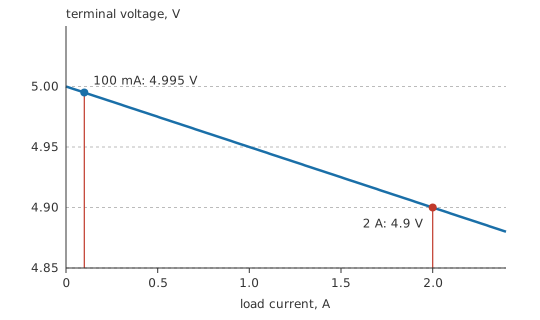
A supply with an open-circuit voltage of 5 V and an internal resistance of 50 mΩ is loaded first at 100 mA, then at 2 A.
At the light load the terminal voltage is 4.995 V; at the heavy load it is 4.9 V. Expressed as a fraction of the loaded value, the change is 1.94 %.
That percentage carries exactly the information the internal resistance carries, printed in the form a datasheet uses. A supply quoting a regulation figure is telling you its output impedance without using the word.
The model reaches a long way past batteries. Thévenin's theorem proves that any network of sources and resistances, seen from two terminals, behaves exactly as one ideal voltage source in series with one resistance. The two-component model is therefore the general form of every linear source, and learning it properly pays off far outside battery work.
It has a dual, as well. A current source holds current rather than voltage, and a real one is modelled as an ideal current source in parallel with a resistance. Both descriptions fit the same physical source and convert into each other exactly — see source transformation and Norton's theorem.
The model does hold one quantity fixed that is not fixed at all: the internal resistance itself. A battery's rises as it discharges, rises sharply as it gets cold, and rises permanently as it ages. A regulator's effective output impedance depends on load current, on frequency, and on whether its control loop is still working in its linear region.
Frequency is the reason decoupling exists. A regulator corrects slowly, so a load that changes in nanoseconds sees not the regulator but the impedance of the path to it — inductance, mostly. Local capacitance acts as a fast source that supplies the transient until the regulator catches up, which is the actual job of a decoupling capacitor.
Real sources also have hard limits the model does not express. A bench supply has a current limit beyond which it stops being a voltage source and becomes a current source. A battery has a chemistry-dependent maximum discharge rate. A solar panel is not a voltage source at all across most of its curve. Everything the linear model says applies inside the intended operating region, and it says nothing about the edges.
Professional
What a real supply is actually specified by
Load regulation describes the change with current at fixed input. Line regulation describes the change with input voltage at fixed load. Both are quoted, and a supply can be excellent at one and mediocre at the other; which of them matters depends on whether your load or your input is the thing that moves.
Neither says anything about what happens during a step, and the step is often what decides whether a design works. A processor waking from sleep can change its current draw by amperes in nanoseconds. What the rail does during that step — how far it dips, how long it takes to recover, whether it overshoots on the way back — is a control-loop property, and it is measured on a scope rather than read from a table.
Under fault or overload, a supply either limits current at a set value, folds back to a lower one, or shuts down and retries. Each behaviour interacts differently with a load that has an inrush current, and a supply that folds back can fail to start a load it is perfectly capable of running. Current limiting develops this.
Internal resistance sets the fault current as well as the sag. For the car battery above, dividing the open-circuit voltage by the internal resistance gives a short-circuit current of 600 A, delivering 7.2 kW into the fault. A dropped spanner across a battery terminal welds itself in place for that reason, and battery systems need fusing sized against the fault current rather than the working current.
Safety
The fault current above is the output of an internal-resistance model, arrived at on paper. Confirming it by experiment is never acceptable. Deliberately shorting a battery of any size — lead-acid, lithium, or a large capacitor bank — produces molten metal, expelled electrolyte and, with lithium-ion, a thermal runaway that sustains itself on the cell's own oxidiser. Water will not quench that internal reaction, which is where the folk rule "never use water on a lithium fire" comes from; the rule is misapplied. Flooding with water is the standard way to fight a lithium-ion fire, because it cools the cells that have not gone yet. The genuinely water-reactive case is lithium metal, found in primary (non-rechargeable) cells.
Remove rings, watches and metal bracelets before working near battery terminals; a ring bridging a terminal carries this current through your finger. Cover unused terminals, work with insulated tools, and fit protection as close to the source as the installation allows. A battery is a low-voltage device and a very high-energy one, and the two facts mislead people in opposite directions. General practice is in electrical safety fundamentals.
Wiring two supplies in parallel does not make them share the load. The one with the marginally higher output voltage takes it all until it hits its limit. Sharing has to be built in: droop, an intentional output impedance that lets the voltages converge, or an active current-sharing loop, or diodes that accept a forward drop to enforce independence.
Some of what matters belongs to the system rather than to the supply. Multi-rail designs care about the order rails come up and go down, because a chip powered on one rail and driven from another can be damaged by the wrong order. Hold-up time — how long the output stays in regulation after the input disappears — is set by bulk capacitance, and it decides whether a brief mains dip passes unnoticed or ends in a reboot.
A switching supply's output carries ripple at its switching frequency. A linear regulator downstream can remove that, but only within its own power-supply rejection ratio, which falls with frequency. Analog and RF blocks are often given a local regulator specifically to buy that rejection, at the cost of the dropout voltage it needs to work.
Common mistakes
- Testing a battery open-circuit — a nearly exhausted cell reads close to nominal until current is drawn. Test under load, or measure internal resistance.
- Treating internal resistance as fixed — it rises with discharge, with cold and with age, and a battery that fails in winter often measured fine in summer.
- Blaming the source for a drop caused by the path — cable, connectors, fuse holders and switch contacts all add to the same total the load sees.
- Paralleling two voltage sources directly — the higher one delivers everything and may drive current into the lower. Sharing needs droop, active balancing or diodes.
- Reading steady-state regulation as transient performance — a supply with excellent regulation figures can still dip badly on a fast load step. Those are different specifications.
- Ignoring the current limit — beyond it, a voltage source stops being one, and a load with high inrush may never start.
Frequently asked questions
What is a voltage source?
A device that maintains a specified voltage across its terminals and supplies whatever current the load requires at that voltage. An ideal one does so without limit; every real one has an internal resistance that makes its output fall under load.
What is internal resistance?
The effective resistance in series with the ideal part of a real source. Current through it produces a drop inside the source, so the terminal voltage is always lower than the open-circuit voltage.
Why does a battery read the right voltage but fail under load?
Because the open-circuit reading measures only the electromotive force. A degraded cell can retain nearly its full EMF while its internal resistance has risen enough to collapse the voltage as soon as current is drawn.
Can two voltage sources be connected in parallel?
Not directly, unless they are designed for it. Any difference in output voltage drives current from one into the other, limited only by their internal resistances. Sharing requires droop, active balancing or blocking diodes.
What does load regulation mean on a datasheet?
How much the output voltage changes between a stated light load and a stated heavy load. It is the source's internal resistance expressed as a percentage, and it says nothing about behaviour during a fast load step.