
Quick Answer
A bench power supply is an adjustable source with two settings, a voltage and a current limit, and it holds whichever of the two the connected load permits. Light loads get the voltage that was set. Heavier loads get the current limit instead, at whatever lower voltage delivers it.
Intuition
The limit knob is the one that matters
A bench supply gives you a voltage you choose, from a mains socket, with a display reporting what your circuit is actually taking. That much is plain from the front panel. What is not plain is the second control, and it is the one that decides whether a wiring mistake costs you an afternoon or a board.
Set the voltage to 5.00 V and the current control to 500 mA and you have not set two independent things. You have named a ceiling on each, and the supply keeps whichever one it can. Connect something that wants less than the limit and the output sits where you put it. Connect something that wants more, and the supply abandons the voltage rather than exceed the current: it falls to whatever value delivers exactly 500 mA, and stays there.
Cruise control that also has a throttle ceiling behaves the same way. On the flat it holds the speed you dialled in. On a climb steep enough that holding the speed would need more throttle than it is permitted, it stops trying, sits at its ceiling, and lets the speed fall away. The car has not failed. It is obeying the tighter of two instructions.
The two states have names. Holding the voltage is constant voltage; holding the current is constant current; and every bench supply carries a lamp or a legend saying which one it is in at that moment. Looking at that indicator before believing the voltage display is the habit this lesson exists to build.
Practitioner
Setting up before anything is connected
The settings go in while the output terminals are bare, because both of them are easier to get right without a circuit reacting to them.
- Work out what the circuit should draw. A rough figure is enough. Add up the quiescent currents on the schematic, or take the number from a similar board you have already run.
- Set the voltage with the output off and nothing connected. The display reads the set point when no load is present, which is the one moment it cannot be pulled down by anything.
- Set the current limit to roughly one and a half times the expected draw. Enough headroom for start-up surges and inrush, not enough to feed a short circuit for long.
- Check the polarity at the terminals before the leads reach the board. Reversed supply rails destroy semiconductors faster than any limit can react.
- Enable the output and read the mode indicator first, not the voltage. Constant current on a board you expected to sit in constant voltage means something is wrong, and it means it before anything gets hot.
- Compare the current reading against your estimate. A figure well under it usually means a connection that is not made; a figure at the limit means a fault.
- Turn the output off, not the mains switch, between changes. Switching the mains discharges the output capacitor through your circuit on the way down, in an order nothing designed for.
Two relationships do all the arithmetic. The load resistance and the set voltage fix the current:
and the current, multiplied by the voltage actually across a part, gives the heat it has to get rid of:
Worked example — A five-volt board with a solder bridge on its rail
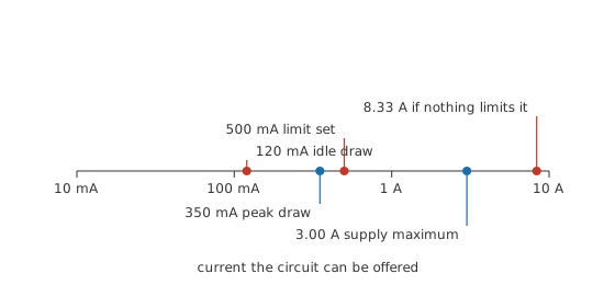
The board idles at 120 mA and peaks at 350 mA, so the supply goes to 5.00 V with the limit at 500 mA, comfortably above the peak.
A bridge of solder across the rail adds a path of 0.60 Ω between the two supply terminals. From an unlimited source, that path would take 8.33 A and turn 41.7 W into heat in a blob of solder the size of a grain of rice. Both figures are arithmetic on the resistance of the bridge, not readings from a bench.
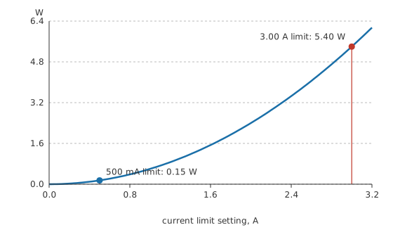
With the limit set, the supply refuses to supply more than 500 mA. The rail collapses to 0.30 V and the bridge dissipates 0.15 W, which it can sit at indefinitely while you find it. The mode indicator switched to constant current the instant the output came on, and the voltage display told the same story by reading far below the set point.
Safety
A single channel at low voltage is about as safe as bench equipment gets, and two things change that. Stacking channels, described in Layer 3, puts 60.0 V between two terminals that each looked harmless on their own, and there is no indication on either front panel that it has happened. From roughly sixty volts up, treat the output as something to be switched off before it is touched, and route the leads so that neither hand has to cross the other.
The second is the output capacitor. It holds charge after the output is switched off and after the mains is removed, and the current limit has no authority over what it releases in the first instant of a short. Switching the output off is therefore not itself the control: prove the terminals dead with a meter before you touch them, the same habit measuring V, I and R and continuity and diode test both build for exactly this reason. Layer 4 puts a number on that energy.
The mains side of the instrument is not user-serviceable. A supply with a damaged lead or a cracked case goes to a repairer, and the electrical safety fundamentals apply to it exactly as they do to any other mains-connected equipment.
Engineer
Inside the crossover
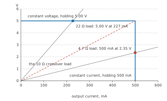
There is one load resistance at which the two ceilings meet. Divide the set voltage by the set current and you have it: 10 Ω for the settings above. Any load larger than that draws less than the limit, so the voltage survives. Any load smaller draws more if allowed to, so the current wins instead.
A 22 Ω resistor across those settings takes 227 mA, well inside the limit, and reads the full 5.00 V. Replace it with 4.7 Ω and the supply hands over 500 mA at 2.35 V instead. The second reading is not a fault in the instrument and not a fault in the resistor. It is the only pair of values that satisfies both ceilings at once.
The volts that never arrive
The number on the display is the voltage at the supply's terminals, and your circuit is at the far end of a pair of leads. Those leads, their crocodile clips and the contact where they meet the board add up to a resistance in series with everything, and the drop across it grows with the current:
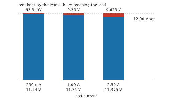
Take 0.25 Ω for a pair of thin leads with tired clips, from a supply set to 12.00 V. At 250 mA the leads keep 62.5 mV and the board sees 11.94 V, which nobody would notice. At 1.00 A that becomes 0.25 V and 11.75 V. At 2.50 A the leads have taken 0.625 V and the board is running on 11.375 V, while the front panel still says otherwise.
Remote sense is the cure on supplies that offer it. A second, thin pair of wires runs from the supply's sense terminals to the point on the board where the voltage matters, carrying almost no current and therefore losing almost nothing. The regulator then works to hold the voltage at the far end of the heavy leads rather than at its own terminals, and raises its output by exactly the drop.
Where the heat goes
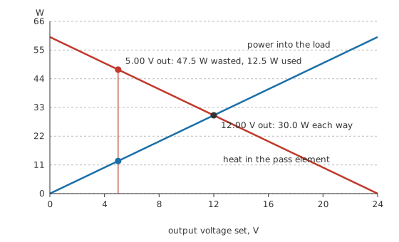
A linear supply produces its output by burning the difference. An internal rail sits at some fixed voltage — take 24.0 V — and a transistor between that rail and the output terminal drops whatever is left over. At 2.50 A and an output of 12.00 V, the transistor takes 30.0 W, matching what the load gets. Turn the output down to 5.00 V and the transistor now takes 47.5 W while the load receives 12.5 W, so most of the mains energy is going into a heatsink.
Switching supplies avoid that by chopping rather than burning, which is why they are smaller and cooler at the same rating. They pay for it in output noise, and a low-noise analog circuit is one of the places where a linear supply is still worth its heatsink.
Two channels
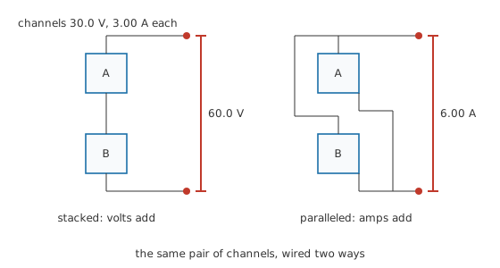
Most bench supplies have two independent outputs, and they can be joined. Wire the negative of one to the positive of the other and the voltages add: two channels of 30.0 V give 60.0 V across the outer pair of terminals. Wire both positives together and both negatives together and the currents add instead, so two channels of 3.00 A can supply 6.00 A.
Paralleling only works cleanly on supplies that offer a tracking or master-slave mode. Two independent regulators told to hold the same voltage will not agree exactly, and the one set fractionally higher supplies everything until it reaches its own limit.
Professional
Where a bench supply stops behaving like a source
The current limit is a control loop, and a control loop takes time to respond. Faster than a human, slower than a semiconductor junction: a device that fails short can pass a great deal of current in the microseconds before the regulator catches up, and it will already be finished when it does. A limit protects wiring, tracks and your own patience far better than it protects the part that started the fault.
Some of that current does not come from the regulator at all. There is a capacitor across the output terminals to keep the impedance low at high frequency, and its charge is available instantly:
A 1000 µF output capacitor charged to 30.0 V holds 0.45 J, and every joule of it is delivered into a short before the limit has any say. This is the reason a supply set to a low current limit can still weld a probe tip to a track, and the reason an output should be switched off rather than merely turned down before anything is rewired.
Remote sense has a failure mode of its own. If a sense wire falls off, the regulator sees zero volts at the point it is trying to control and raises its output to correct it, taking the real terminals up to whatever the supply can produce. Sense leads are therefore made before the output is enabled and removed after it is disabled, and a supply left in remote sense with nothing on the sense terminals is a trap set for the next person.
Regulation and noise are specified quantities rather than perfect ones. Load regulation quotes how far the output moves between no load and full load; line regulation quotes how far it moves when the mains does; and the ripple and noise figure quotes what is left riding on top. All three matter when the circuit being powered is itself a measuring instrument, and none of them appears on the front panel. The oscilloscope is what shows the last of them.
Programmable instruments and electronic loads change the job again. A supply with a remote interface can step through a sequence of voltages while something else records what the circuit did, which turns a bench session into a repeatable test. An electronic load does the complementary trick, presenting a programmable resistance, current or power to something you are characterising. Four-quadrant instruments go further still and will absorb current as well as supply it, which is what testing a battery charger or a regenerative drive actually needs.
Bench supplies are also the wrong instrument for some jobs that look like theirs. A circuit that needs a defined current rather than a defined voltage is better served by a real current source; constant-current mode on a bench supply is a limit that happens to be active, not a precision current reference. And a supply is not a signal source: a waveform of any kind belongs to the function generator.
Common mistakes
- Reading the voltage display and ignoring the mode lamp. A supply in constant current is showing you what the fault permits, not what you set. The lamp changes before the number does anything alarming.
- Setting the current limit to maximum "so it does not get in the way". That converts a protective instrument into an unprotected one, and the first thing it protects is the wiring you spent the afternoon on.
- Trusting the terminal voltage as the board voltage. At any real current the leads keep a share, and remote sense or a meter at the load is the only way to know how big a share.
- Stacking two channels and forgetting. Sixty volts appears between two terminals with nothing on either display to say so, and both channels look exactly as they did before.
- Rewiring with the output merely turned down rather than switched off. The output capacitor does not care what the knob says.
- Paralleling two ordinary channels without a tracking mode, then wondering why one of them is doing all the work while the other sits idle.
Frequently asked questions
What does the CC light on my bench supply mean?
The supply has hit the current limit you set and is holding that current rather than the voltage. The output voltage will be lower than the set point, sometimes far lower. On a circuit you expected to sit in constant voltage, it means a short, a reversed part or a limit set too low.
How high should I set the current limit?
Around one and a half times what the circuit should draw at its busiest. That covers inrush and start-up surges while still cutting a genuine fault down to something harmless. When you have no estimate at all, start low, enable the output, and raise the limit until the circuit comes alive.
Why is the voltage at my board lower than the supply says?
The leads between them have resistance, and the drop across it grows with current. Long thin leads and worn crocodile clips make it worse. Measure at the board rather than the terminals, or use the supply's remote sense terminals if it has them.
Can I use a bench supply as a battery charger?
For some chemistries and with care, because constant current followed by constant voltage is the shape most charging profiles take. It has no cell protection, no termination detection and no temperature monitoring, so it is a poor substitute for a charger designed for the pack. Lithium chemistries in particular need a charger that knows when to stop.
Why does my supply get hot at low output voltages?
A linear supply drops the difference between its internal rail and your output across a transistor, and that transistor dissipates the difference multiplied by the current. Turning the output down increases the difference, so the heat goes up as the useful power goes down.