
Quick Answer
Continuity mode beeps when the resistance between the probes falls below a threshold the meter sets, so it answers whether two points are joined. Diode mode pushes a small fixed current through whatever is between the probes and reports the voltage that took, which identifies a junction.
Intuition
Asking whether two points are joined
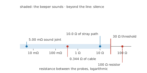
Half of fault-finding is the question "does this reach that?" A track, a wire in a loom, a fuse, a switch contact, a connector pin: each is meant to be a piece of metal joining two places, and each fails by ceasing to be one. A sound joint measures a few thousandths of an ohm, 5.00 mΩ or better; anything approaching the 100 Ω of an ordinary small resistor is not a joint at all.
The continuity range answers that question without asking you to read anything. The meter watches the resistance between its probes, and when it falls below a threshold of its own it sounds a tone. You can keep your eyes on the probe tips, which on a dense board is most of what makes the feature worth having.
A doorbell answers the same kind of question. It tells you someone is at the door. It does not tell you who, or how many, or whether they are welcome. The beeper is exactly that useful and exactly that limited: it says "joined", it does not say "joined well", and Layer 3 has the numbers on how wide the gap between those two statements can be.
The diode range sits next to it on the switch and does something different. Rather than judging a resistance against a threshold, it pushes a small fixed current through whatever is between the probes and reports the voltage that took. A piece of wire takes almost none. A silicon junction takes 0.65 V or thereabouts, and takes it in one direction only. That asymmetry is how the range identifies a junction and tells you which way round it is fitted.
Both ranges need the circuit dead. They work by driving the meter's own current through the part, and any other current present makes the answer meaningless.
Practitioner
Using the beeper without being fooled by it
- Switch off, and discharge anything that stores energy. Both ranges assume nothing else is driving current through the part.
- Prove the meter on itself. Touch the probes together: the beeper should sound and the display should read close to zero. That one action tests the meter, the leads and the fuse before you trust any of them.
- Note what the shorted-lead reading actually is. That figure is in every subsequent low-resistance reading, and Layer 3 shows when it matters.
- Test from the two ends that matter, not from the two ends that are convenient. A connector proved good at its own pins says nothing about the crimp behind them.
- Wiggle while you listen. An intermittent joint that is sound while still shows itself as a break in the tone under a little movement, and this is the one measurement where provoking the fault is easy.
- On the diode range, take both directions. One reading is a forward voltage and the other should be an open circuit. Two open readings mean an open junction. Two forward readings mean something other than a single junction is between the probes — anti-parallel junctions, a protection device, or the wrong pair of pins — because an actually shorted junction reads near zero and beeps in both directions, not a forward voltage.
- Where the answer surprises you, lift one end. Everything else joining those two points is in parallel with the part, and that is how a broken track can beep.
The diode range's own arithmetic is small. It drives a known current through the junction, so the power the junction absorbs during the test follows directly:
Worked example — Identifying an unmarked junction
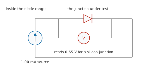
Set the meter to its diode range, which pushes 1.00 mA through whatever is between the probes.
Red on one lead of the unknown part and black on the other gives 0.65 V. Swap the leads and the display shows an open circuit. That pair of readings identifies a silicon junction conducting from the red probe to the black one, so the red probe is on the anode.
During the forward reading the junction is dissipating 0.650 mW, which is far below anything that could disturb it. The test is safe for the part in a way that a resistance range on a powered board is not.
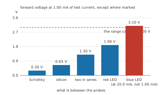
A reading of 0.30 V instead would point to a Schottky diode, 1.90 V to a red LED, and 1.30 V to two silicon junctions in series, which is what the base-to-emitter path of some transistors and the input of some protected inputs look like. Forward readings in both directions point to something other than a single junction — anti-parallel junctions, a protection device, or the wrong pins — since a genuinely shorted junction reads near zero and beeps both ways rather than showing a forward voltage either way. Open readings in both mean it is open or that its forward voltage is above what this range can reach.
Safety
Neither range belongs on a live circuit. Both work by driving the meter's own current through the part, and a circuit supplying its own current gives a reading that means nothing, damages the meter, or both. Isolate first, then discharge, then measure.
Bulk capacitors are the usual trap here, because a board that has been switched off for a minute can still be holding a serious charge. Prove the node dead on the volts range before switching to continuity, and treat a board with a failed bleed resistor as charged indefinitely. The full working practice is set out in electrical safety fundamentals.
One more thing the beeper cannot do: it cannot tell you a circuit is safe to touch. It answers a question about metal, not about potential.
Engineer
Why one junction reads two ways
The two ranges differ in one respect that explains most of their behaviour: how much voltage each is willing to put across the probes.
The resistance and continuity ranges open at around 0.25 V, deliberately less than the 0.65 V a silicon junction needs. That choice means semiconductors near the part you are measuring stay switched off, so a resistance reading describes resistors rather than the whole board waking up. The same choice means a junction measured on the ohms range reads as an open circuit in both directions, which looks like a fault and is not one.
The diode range opens at 3.00 V or so, comfortably past a silicon junction, which is why the same part now conducts and reports a sensible number. It is the same instrument and the same part; only the voltage the range is prepared to offer has changed.
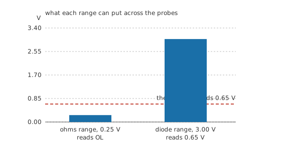
That ceiling has a consequence at the other end. A blue or white LED's forward voltage is usually catalogued at 20.0 mA, a much larger current than the 1.00 mA this range tests at, and comes out around 3.10 V there — above what many diode ranges can supply even before the current is accounted for. At this range's own test current a blue or white LED typically needs somewhat less, but often still more than a 3 V range has to give, so a perfectly good one commonly reads as an open circuit in both directions. An open reading on a blue or white LED is therefore weak evidence of a fault; the meter may simply have run out of voltage.
What the threshold hides
The beeper's threshold is somewhere around 30 Ω on a typical handheld meter, and every meter states its own. Everything below it produces one identical tone, which means four decades of resistance are compressed into a single yes.
Take a conductor 10.0 metres long and half a square millimetre in section, in copper, whose resistivity is about 17.2 nΩ·m:
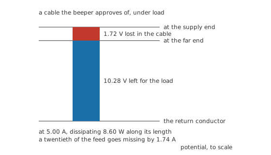
which gives 0.344 Ω. The beeper approves of it without hesitation. Put 5.00 A through it and it keeps 1.72 V of a 12.0 V feed for itself, delivers 10.28 V at the far end, and turns 8.60 W into heat along its length. A cable that beeps can still be entirely unfit for the job it was chosen for. Wire resistance and voltage drop treats the sizing question properly.
The other path across the same two pads
The beeper measures everything between the probes, and a board is full of paths a schematic does not draw attention to. A sound track of 50.0 mΩ shunted by 10.0 Ω of some other route measures the two in parallel:
giving 49.8 mΩ. Break the track and the meter now sees only the 10.0 Ω route, still comfortably below the threshold, still beeping. The tone is identical and the track is severed.
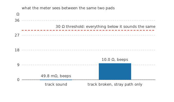
Reading the displayed resistance rather than listening to the tone catches this immediately, and it is the reason experienced people keep half an eye on the number even while working by ear. Where the number is ambiguous, lifting one end of the suspect path settles it, exactly as in-circuit testing sets out.
Professional
Past yes-or-no
Continuity and diode test are the two cheapest questions a meter can ask, and their limits mark where the rest of the bench starts.
Neither says anything about a joint under load. A dry solder joint, a corroded crimp and a spring contact that has lost its tension all pass continuity and all fail at working current, because their resistance is small until heat and current make it larger. A four-wire measurement gets closer, and a load test closer still: pass the real current and watch the drop.
Neither says anything about timing. A relay contact that closes fifty milliseconds late is a perfect short circuit by the time the beeper hears about it, and a switch that bounces for a few milliseconds beeps as one clean connection. Both need the oscilloscope to be seen at all.
The diode range's reach into semiconductors is real but shallow. Two junctions in the right relationship look like a bipolar transistor, and the range will find the base and tell you the polarity, but gain, leakage and breakdown are all invisible to it. A field-effect transistor's gate reads as an open circuit that happens to store charge, so the readings jump about until the gate is discharged. Anything with protection diodes across its inputs reads as junctions everywhere, whatever the part actually is.
Capacitance is a related blind spot with a useful side effect. A large capacitor between the probes makes the beeper sound briefly while the meter's test current charges it, then stop. That momentary chirp is not a short circuit, and mistaking it for one is a standard beginner's afternoon.
Two ranges take these questions further, both later in this department. An LCR meter drives the part at a stated frequency and separates the resistive part of its behaviour from the reactive part, which is how a capacitor's series resistance and an inductor's quality get measured rather than guessed. A clamp meter answers the load question without breaking anything, by reading the current a suspect joint is actually carrying while the equipment runs.
Common mistakes
- Trusting the tone and never looking at the number. The beeper compresses four decades into one sound, so a poor joint and a perfect one are indistinguishable by ear.
- Using continuity on a live circuit. The range drives its own current and expects nothing else to be driving any, so the reading is meaningless and the meter is at risk.
- Reading a junction on the ohms range and calling it open. That range deliberately cannot reach a silicon junction's forward voltage, which is what keeps semiconductors quiet during ordinary resistance measurements.
- Condemning a blue LED that reads open on both directions. Many diode ranges cannot supply the three volts and more it needs, and an open reading on those is the meter's limit rather than the part's.
- Hearing the chirp of a capacitor charging and reporting a short circuit. Watch whether the tone stops, and whether the displayed resistance climbs while you watch.
- Proving a wire good at the two points that were easy to reach. The fault is usually at the crimp, the connector or the point where the loom passes through a bulkhead.
Frequently asked questions
What resistance makes a multimeter beep?
It varies by meter, and each one states its own threshold. Somewhere in the tens of ohms is typical. Everything below it produces the same tone, so the displayed number carries information the beeper does not.
Why does my diode read OL on the resistance range?
Because that range applies less voltage than a junction needs to conduct, on purpose, so that semiconductors near a resistor being measured stay switched off. Use the diode range, which applies enough to turn the junction on.
What should a good silicon diode read on the diode range?
Around 0.6 to 0.7 volts one way round and an open circuit the other. A Schottky reads lower, an LED considerably higher, and two junctions in series read about twice a single one. A forward voltage in both directions is not a short: a real short reads near zero and beeps both ways, so two readings like that usually mean the probes are seeing anti-parallel junctions, a protection device, or the wrong pins instead of one clean part. Open readings in both usually mean an open, unless the part needs more voltage than the range can supply.
Can I test a diode while it is still soldered in?
Sometimes, and the result needs care. Anything in parallel with the junction is measured alongside it, so a low-value resistor across it will mask the reading entirely. A reading that looks wrong is a reason to lift one end rather than a verdict.
The beeper sounds but the circuit still does not work. What now?
Read the number rather than listening. A joint of a few ohms will beep and will still starve a load that needs current. Then check under load: measure the voltage across the suspect joint while the circuit is running, because a resistance that is invisible at the meter's test current shows itself immediately at the real one.