
Quick Answer
A diode is tested by measuring it in both directions with a meter's diode range. A good part gives a forward voltage one way and refuses to conduct the other. The number identifies the type as well as confirming it works, and the ohms range gives an answer that means nothing.
Safety
A diode test drives current into whatever the probes touch, so the circuit must be off and its supply capacitors discharged before you start. That is not a formality: a reservoir capacitor holds its charge long after the power is removed, and a rectifier is usually connected straight to one. Prove the circuit is dead rather than assuming it, and do the proving with the meter on a voltage range, before switching to the diode range.
Intuition
The key tried both ways round
A key that will not turn is either the wrong key, or the right key the wrong way up. You find out by trying it the other way, and the whole diagnosis takes two seconds because the test is symmetric: the answer is in the difference between the two attempts, not in either one alone.
Testing a diode is exactly that. Put a meter across it, note what happens, swap the leads, note what happens again. A working diode gives you a number in one direction and nothing at all in the other, and it is the pair of results that tells you the part is good. Either one alone tells you very little.
Most meters have a range marked with a diode symbol, and it exists for this. On that range the meter pushes a small, known current through whatever is between the probes and displays the voltage that produces. Point it at a working diode the right way round and the display shows the diode's forward drop. Point it the other way and the diode blocks, the meter cannot push its current through, and the display gives up.
The number is worth more attention than most people give it, because it does not merely say "working". A silicon diode, a Schottky and an LED all read differently, and so does a part with two junctions in series. The reading identifies what you are holding.
Practitioner
The two readings, and what the number is
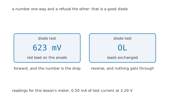
A number one way and a refusal the other: that is a good diode.
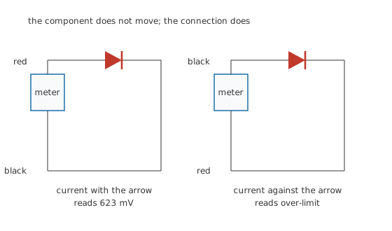
The component does not move; the connection does.
The loop is two elements: the meter and the diode. Whatever the meter pushes has to go through the part, so there is nothing else for the reading to describe.
The forward number is the drop at the meter's test current, not at yours. That distinction is where most confusion about diode testing lives.
Worked example — What this meter reads on three kinds of part
This lesson's meter pushes 0.50 mA with 3.20 V of compliance, and the thermal voltage at 300 K is 25.85 mV.
A silicon diode that drops 0.70 V at 10 mA with an ideality factor of 1.0 therefore reads 623 mV.
A Schottky that drops 0.35 V at the same reference, ideality 1.05, reads 269 mV.
A red LED at 2.05 V and ideality 2.0 reads 1.895 V, and on many meters it will visibly glow while you do it.
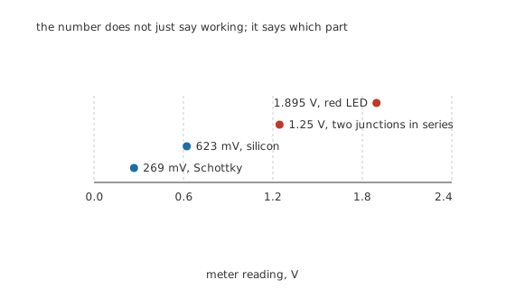
The number does not just say working; it says which part.
A part reading 1.25 V has two junctions in series, which is what a bridge rectifier's diagonal terminals or a dual diode in one package looks like. Nothing is wrong; you are measuring two of them.
Engineer
Reading the result properly
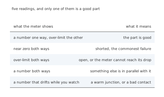
Five readings, and only one of them is a good part.
Near zero in both directions is a short, and it is the commonest way a diode fails. It matters because a shorted rectifier presents as a blown fuse or a hot transformer, and the diode is not the obvious suspect.
Over-limit in both directions is either an open part or a meter that cannot reach. With 3.20 V of compliance this meter manages an LED at 1.895 V comfortably, but a blue LED or a series string can exceed it, and the honest reading then is "this meter cannot test this part" rather than "this part is open".
A number in both directions means something else is in parallel.
Worked example — Why an in-circuit reading may describe the wrong thing
Leave the diode soldered in with a 1.0 kΩ path across it. The meter's 0.50 mA takes the easier route and develops 500 mV across that resistor.
That is below the diode's own 623 mV, so the diode never conducts and the reading describes the resistor.
Any parallel path low enough to develop less than the diode's drop at the test current hides the part completely.
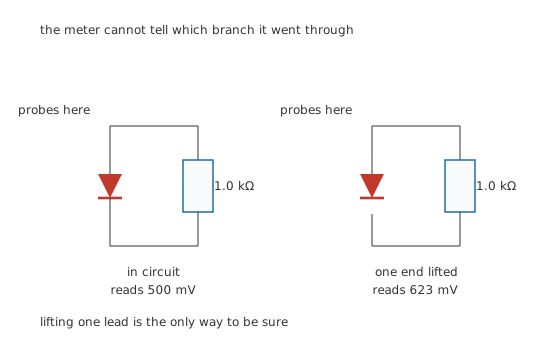
The meter cannot tell which branch it went through.
Lifting one end is the only certain answer. An in-circuit reading that looks like a diode is worth something; an in-circuit reading that does not is worth nothing until the part is isolated.
Why the ohms range answers a different question
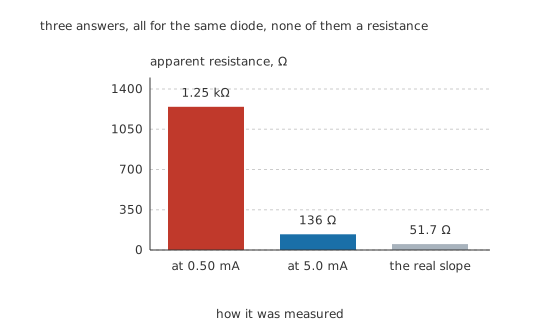
Three answers, all for the same diode, none of them a resistance.
An ohms range pushes a current, measures the voltage and divides. For a resistor that gives the same answer whatever the current. For a diode it does not, because the diode's voltage barely moves while the current changes by decades.
Worked example — The three numbers, none of which is a resistance
At 0.50 mA the reading of 623 mV divides out to 1.25 kΩ.
At 5.0 mA the same diode reads 682 mV, which divides out to 136 Ω.
Those differ by 9.13 times, for the same part on the same day. The diode's actual small-signal resistance at the lower current is 51.7 Ω, which is neither of them.
A diode has no resistance to measure, so the ohms range's answer is an artefact of the current the meter happened to use. Use the diode range, which reports the voltage and lets you interpret it.
Professional
What the test does not tell you
The two-reading test is fast, decisive and incomplete, and the gap matters more on some parts than others.
It says nothing about the reverse rating. The meter applies 3.20 V. A diode rated for a hundred volts that breaks down at twenty passes this test perfectly and fails in the circuit. Nothing a handheld meter can do finds that, and a curve tracer or a bench supply with current limiting is the tool for it.
It says almost nothing about leakage. In the reverse direction the meter is looking for current through its own input, and a small leakage produces a reading that is easy to misread.
Worked example — What a leaky part might show
A part leaking 100 nA into a meter's 10 MΩ input would develop 1.0 V.
Whether that appears as a reading or as over-limit depends entirely on how the meter's diode range is built, and different meters answer differently. Treating a reverse reading as a leakage measurement is not safe.
It says nothing about speed. Reverse recovery, junction capacitance and switching behaviour are invisible to a DC test. A slow diode substituted into a fast circuit passes every check here and fails in service, which is why Schottky and fast-recovery parts cannot be verified by meter.
It says nothing about the part under load. The drop at 0.50 mA and the drop at an amp are different numbers, and the difference is the whole of diode I-V characteristics.
Three practical habits
Test the suspect against a known-good part of the same type. Two readings a few tens of millivolts apart mean nothing; two readings differing by a factor are worth investigating. This turns an absolute measurement into a comparison, which is what a handheld meter is actually good at.
Watch for the reading drifting. A number that creeps while you hold the probes is usually your own hand warming the junction, which is real physics rather than a fault: the drop falls about two millivolts per degree. It can also be a poor probe contact, and it is worth knowing which before condemning anything.
Test bridge rectifiers terminal by terminal. A packaged bridge has four diodes and four terminals, and each of the four AC-to-DC pairs should behave like one diode. A reading of 1.25 V across the two AC terminals is the two series diodes and is correct; a short there is not.
When the meter is not enough
Reach for a bench supply and a series resistor when the question is about reverse voltage, current capability or anything time-dependent. Set a current limit, bring the voltage up gently, and watch. That measures the part in the region it will actually work in, which no diode range does, and the continuity and diode test lesson covers what the meter's ranges are really doing while you decide.
Common mistakes
- Testing in circuit and trusting the answer — a 1.0 kΩ path across the diode develops only 500 mV at the test current, which is less than the diode's 623 mV, so the reading describes the resistor.
- Using the ohms range on a diode — the same part reads 1.25 kΩ at 0.50 mA and 136 Ω at 5.0 mA, a factor of 9.13, because a diode has no resistance to report.
- Reading over-limit as a fault — a meter with 3.20 V of compliance cannot test a blue LED or a series string, and the honest conclusion is that the meter cannot reach, not that the part is open.
- Assuming a passed test means a good part — the test says nothing about the reverse rating, the leakage, the speed or the behaviour at real current.
- Probing a circuit that has not been proved dead — a reservoir capacitor stays charged after the supply is removed, and a rectifier is usually connected directly to one.
Frequently asked questions
How do I test a diode with a multimeter?
Use the diode range, put the red lead on the anode and the black on the cathode, and note the reading. Then swap the leads and note it again. A good part gives a forward voltage one way, typically a few hundred millivolts for silicon, and over-limit the other. It is the pair of readings that matters.
What should a good diode read?
For this meter's 0.50 mA test current: about 623 mV for an ordinary silicon diode, 269 mV for a Schottky, 1.25 V for two junctions in series, and 1.895 V for a red LED. Other meters use other test currents and read a little differently, so compare against a known-good part of the same type rather than against a remembered number.
Why not use the ohms range?
Because a diode does not have a resistance. An ohms range divides the voltage it measures by the current it pushed, and since a diode's voltage hardly changes while the current changes by decades, the answer depends entirely on which range you picked. The same diode reads 1.25 kΩ or 136 Ω depending on the current.
Can I test a diode without unsoldering it?
Sometimes, and you cannot trust the result unless it looks like a diode. Anything in parallel that develops less than the diode's drop at the meter's test current hides the part completely. If the in-circuit reading looks like a working diode you have your answer; if it does not, lift one end before concluding anything.
My diode passes the meter test but the circuit still fails. Why?
Because the test only checks conduction one way at very low current. It says nothing about the reverse breakdown voltage, about leakage, about switching speed, or about the drop at the current the circuit actually uses. Any of those can be wrong in a part that measures perfectly on a meter.