
Quick Answer
Measuring a part without unsoldering it measures the part and everything the board joins to it. The reading can only ever come out low, never high, which makes some in-place results decisive and others meaningless. Knowing which is which decides whether the iron has to come out at all.
Intuition
Two probes, and everything between them
Putting two probes on a resistor that is still soldered to a board measures the resistor and every other route between those same two points. The meter has no way to tell them apart. It pushes a small test current out of one probe, waits to see how much comes back at the other, and reports the resistance that would explain the result. If some of that current went the long way round through the rest of the stage, the number on the screen belongs to the board rather than to the part.
Before any of this, switch the equipment off and let the bulk capacitors discharge. A resistance measurement on a live board reads nonsense, and a charged reservoir capacitor stays dangerous long after the mains lead is out; electrical safety fundamentals sets out the practice.
Take a 5.1 kΩ resistor whose two nodes happen to be joined again, elsewhere in the same stage, by a chain of 2 resistors of 8.2 kΩ each.
Those two are 16.4 kΩ in series, sitting across the part, and the meter adds them in without being asked. It reads 3.89 kΩ.
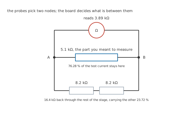
The reading is a real measurement of a real thing. The thing is not the part.
Split the test current between the two routes and 76.28 % of it stays in the part while 23.72 % comes back through the board.
Put that beside the error and it is the same number. The reading is low by 23.72 % of the marked value, and 23.72 % is exactly the share the board took. That is no coincidence of these particular values: it falls out of the parallel formula for any pair. Whatever fraction of the current escapes is the fraction of the answer you lose.
A meter on a board is a listener at the back of a choir. You can hear perfectly well that something is flat, and you cannot say who. The only certain way to hear one voice is to ask everybody else to stop.
Practitioner
Getting an answer without touching the iron
Unsoldering costs heat, a pad and a joint to remake, so it is worth knowing how much can be settled with the board intact. Three things can, and none of them needs an iron.
The error has a direction. A parallel path can only ever pull a reading down. Adding a route between two points makes it easier to get from one to the other, never harder, so the in-circuit reading is a floor and never a ceiling. That single fact splits the ohms axis in two.
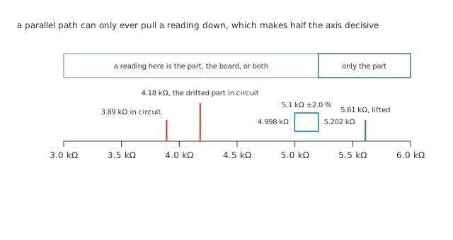
Everything to the right of the band is out of reach of the board. A reading that lands there has nowhere else to have come from.
A 5.1 kΩ part at 2.0 % is allowed to sit anywhere between 4.998 kΩ and 5.202 kΩ.
Read 5.202 kΩ or more on that part in circuit and you are finished: no arrangement of components on that board could have produced it, so the part itself is above its limit. Read anything below the band and you have learned almost nothing, because the board could be responsible for all of it. One side of the band is a verdict and the other is a shrug, and which side you are on costs nothing to check.
Compare against a channel that works. Boards repeat themselves. Where a second identical stage exists, the same measurement on the same node of the good one carries the same parallel paths, so the difference between the two readings is the difference between the two parts.
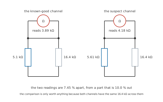
Neither reading is the value of anything. The difference between them is still the fault.
Drift the part to 5.61 kΩ, which is 10.0 % above its marked value and comfortably outside its band, and in circuit it reads 4.18 kΩ. Held up against the marked 5.1 kΩ that number looks harmlessly low, exactly like the healthy channel's 3.89 kΩ. Held up against the healthy channel it is 7.45 % away, and two supposedly identical stages have no business differing by that much. The parallel path dilutes the fault from 10.0 % down to 7.45 %, but it cannot hide it.
Ask the same question twice, with the leads the other way round. Resistance is symmetrical and semiconductor junctions are not. On its resistance ranges the meter puts only about 0.25 V across the circuit, 0.40 V short of the 0.65 V a silicon junction needs to conduct, so nearby junctions stay shut and the reading is honest about them. The diode range has about 3.00 V to spend, which is ample to switch one on. If a resistance reading changes when the probes swap, something is conducting one way and not the other, and the number is not a resistance at all. Continuity and diode test covers what each range is doing.
Engineer
Settle it, bound it, or lift it
Every in-place measurement lands in one of three places, and naming which one before you interpret the number is most of the discipline.
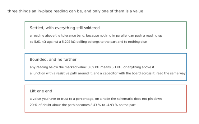
Only the top band is an answer. The middle one is a range, and the bottom one is a job.
The tempting fourth option is to compute the board back out. Rearranging the parallel formula for the branch you want gives the part's value from the reading and the path, and with the true 16.4 kΩ it returns 5.1 kΩ exactly. The catch is that you rarely know the path that well.
Worked example — What a fuzzy path does to a sharp answer
Suppose the schematic pins the parallel path down to 20 %, so the real figure lies somewhere between 13.12 kΩ and 19.68 kΩ. Extracting the part at each end of that range gives 5.53 kΩ and 4.85 kΩ — a spread of 8.43 % to -4.93 % around the part's marked value.
The band is not symmetrical, and it never is. Under-estimating the path costs more than over-estimating it by the same percentage, because subtracting reciprocals runs away as the two get closer together. A part with a tolerance of 2.0 % cannot be judged against a window that wide.
The arithmetic works and the answer is still too soft to use. That is the honest shape of the technique: it tells you when something is definitely wrong, it often tells you which of two boards is the odd one, and it will not hand you a value you can put a tolerance around.
Some parts are worse than others. A resistor at least reads as a resistance. A capacitor is measured through whatever the board puts across it, and the meter must decide whether to call that a series or a parallel arrangement — a choice that can move the reported capacitance by half, as LCR meters sets out; testing capacitors covers which capacitor faults survive being measured in place. Junctions are worse again, since a resistive path around a base-emitter junction drags the apparent forward drop down with it, and testing transistors plots that across a decade of parallel resistance.
Professional
One end, and which one
When the reading has to be trusted, one end of the part comes off the board. Not both, and it matters that not both is enough.
A parallel path needs two nodes to be a path. Break either one and every route around the part opens at the same time, whatever else is soldered to the other end. That is why lifting a single leg restores the measurement completely rather than partly, and why lifting the second one buys nothing but a second joint to remake.
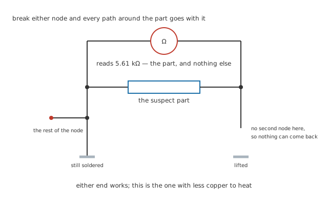
The lifted lead ends in mid-air. That gap is the whole measurement.
Once the leg is clear, the meter reads 5.61 kΩ — the part and nothing else. Set against the 5.202 kΩ ceiling for a 5.1 kΩ part at 2.0 %, that is a verdict with a number attached, which is what none of the in-place readings could give. Measuring voltage, current and resistance covers how the lifted part is then wired up.
Which end to choose is a soldering question rather than an electrical one, since either works. Prefer the end with less copper attached to it. A pad joined to a ground plane sinks heat away as fast as the iron delivers it, so the joint takes longer to melt and the laminate around it takes more of a beating; a pad that feeds one short track gives the joint up quickly. Prefer the end that is not underneath something else, and the end whose pad you can still see when the part is bent up. Soldering basics covers the technique and the damage bad technique does.
The cost is what all the earlier techniques exist to avoid. Every lift puts heat into the laminate, risks the pad's adhesive, and leaves a joint made under diagnostic conditions rather than production ones. On a dense board, creating a second fault while chasing the first is a real risk, which is the real argument for the bounding readings and the comparison: not that they are more accurate, but that they are free.
None of this replaces reading the circuit first, since a reading that looks wrong is often a correct reading of the wrong node. DC troubleshooting plots how a parallel path moves a reading as it varies, and carries the procedure this measurement belongs inside. Testing diodes puts an in-circuit and a lifted junction side by side, and resistor failure modes maps where drifted values actually land. When a reading is off by a few per cent rather than a factor, suspect the instrument instead: accuracy, resolution and measurement error covers an error far smaller than 23.72 % of the reading vanishing into the board.
Common mistakes
- Treating a low in-circuit reading as a fault — it is the expected result. The board is in parallel with the part and pulls every reading down, so a resistor reading below its marked value in circuit is the normal case and says nothing on its own.
- Treating a high in-circuit reading as noise — that one is real. Nothing on the board can raise a reading, so a part reading above its tolerance ceiling in circuit has already failed and needs no further proof.
- Comparing against a channel that is not identical — the technique depends entirely on both nodes carrying the same parallel paths. A different revision, a depopulated option resistor or a link fitted on one board and not the other makes the comparison worthless without making it look worthless.
- Reading a junction on the diode range in circuit and believing the number — the diode range has enough compliance to turn on things you did not intend to include, and a resistive path around the junction drags the displayed drop wherever it likes.
- Lifting both ends out of caution — one end opens every parallel path there is. The second joint is pure cost: more heat, another pad at risk and nothing gained.
Frequently asked questions
Why is the in-circuit reading always low and never high?
Because a parallel path is an extra route, and an extra route can only make it easier to get between two points. Adding any finite resistance across a part lowers the combination below both of them. There is no arrangement of passive components that raises it, which is why a high reading is decisive and a low one is not.
Can I subtract the board's contribution if I know what it is?
Arithmetically yes, and the parallel formula rearranges cleanly for it. In practice the answer is only as good as your figure for the parallel path, and the error grows faster than the doubt that produced it. Use it to decide whether a part is plausible, not to decide whether it is in tolerance.
Does powering the board down actually matter for a resistance reading?
Yes, twice over. The meter's own test current is what a resistance range measures, and any voltage the circuit supplies is added to it, so the result on a live board is meaningless. Bulk capacitors also hold a charge long after the supply is disconnected, and a resistance range is not built to survive being connected to one.
Why does the reading change when I swap the meter leads?
Something in the net is conducting in one direction and not the other, which means a semiconductor junction is in the measurement. A plain resistance does not care which way round it is asked. The asymmetry is a useful result about the topology even when it is a useless one about the value.
Is in-circuit testing the same thing as the automated test a factory does?
No. A production tester grips the board on a bed of nails and guards nodes by driving them, which is what lets it measure one component at a time. A hand meter has two probes and nothing to guard with, so everything here is about living with the paths rather than removing them.