
Quick Answer
Soldering joins two metals with a filler alloy that melts, wets both surfaces and freezes into one continuous piece of metal. The iron heats the joint and the joint melts the solder, so the work is mostly about getting heat into the right place quickly and then leaving.
Intuition
What makes solder stick
Pour water onto a freshly waxed car panel and it stands up in beads, touching as little of the paint as it can. Pour it onto the same panel stripped back to bare metal and it sheets out flat and clings. The water is identical in both cases; what differs is the surface it lands on.
Molten solder behaves the same way, for a related reason. On a clean, hot metal surface it spreads, runs into the corner between a lead and a pad, and forms a thin alloy layer with the metal underneath. On a surface carrying even a whisper of oxide it beads up and sits there, touching but not joined. From above, that bead looks like a joint. It is a drop of frozen metal resting on a dirty pad.
The spreading is called wetting, and everything in the next layer is in service of it. Flux strips the oxide and keeps stripping it while the metal is hot. The heat both melts the alloy and drives the reaction that bonds it to the surface below, and both stop the moment that surface is dirty again — which on hot metal takes seconds.
The temperatures involved sit closer together than beginners expect. The tin-lead eutectic alloy Sn63Pb37 melts at about 183 °C, and the lead-free alloys that replaced it across most manufacturing melt around 217 °C, only 34 °C higher. An iron tip set to 350 °C stands 167 °C above the first and 133 °C above the second, and that headroom is the whole working margin.
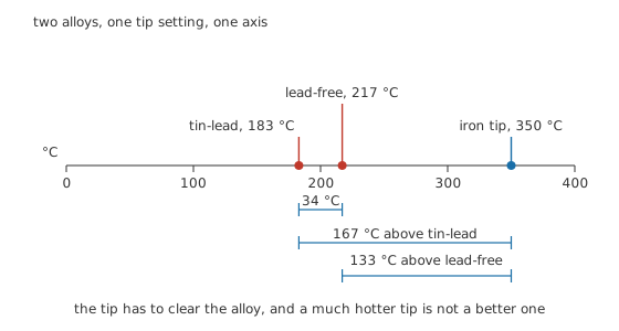
One temperature axis, and the gap you actually get to work in.
Practitioner
Making one joint
The iron does not melt the solder. The iron heats the joint, and the joint melts the solder. Reverse those and you get a bead of alloy dropped onto a cold pad, which is the classic bad joint and looks convincing right up until something asks it to carry current.
- Clean and tin the tip. A tip with a bright coat of solder on it moves heat; a dry, oxidised one barely moves any, and turning the temperature up to compensate makes the oxide worse.
- Get both metals into contact before any heat arrives. A lead that shifts while the alloy freezes gives a dull, grainy joint with a crack running through it.
- Touch the tip to the pad and the lead at the same time. Whichever one you miss stays cold, and a joint is only as good as its colder half.
- Put a little solder into the corner where the tip meets the joint. That small fillet is the thermal bridge the heat crosses; without it the tip touches metal at two or three points and warms almost nothing.
- Feed the solder into the joint on the far side from the tip. If it will only melt against the tip itself, the joint is not hot enough yet.
- Watch for the flow. The alloy goes from a lump to a bright film that runs up the lead and into the corner, and that moment, rather than the melting, is when the joint is made.
- Take the iron away and leave the joint alone while it freezes. Blowing on it or nudging the part produces the crack described in step 2.
How long any of that takes is not a matter of taste. Treat the joint as a small mass warming towards the tip temperature and the answer falls out of a first-order curve, the same shape as an RC charge. Take a joint starting at 25 °C with an illustrative thermal time constant of 1.8 s. A tip at 350 °C carries it past the tin-lead melting point in 1.20 s and past the lead-free one in 1.61 s. Drop the tip to 300 °C and that second crossing moves out to 2.16 s.
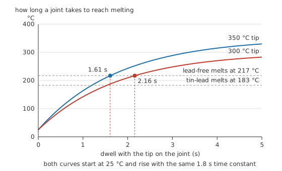
Two seconds is a long time to hold an iron on a small part.
A tip running too cool does more damage than one running slightly hot. It still makes the joint, but it makes it slowly, and keeps everything within a few millimetres warm for the whole of that time.
Safety
A tip at 350 °C looks exactly like a tip at room temperature, with nothing to see or hear until you touch it. The only habit that survives a tired evening is to treat the iron as hot from the moment it is plugged in until long after it is unplugged, and to return it to its stand every time your hand leaves it.
Heated flux gives off fume, and that fume is an irritant rather than something to sit in for an afternoon. Work where the air moves and keep your face out of the plume.
Lead is a genuine health question and not one this lesson is qualified to settle. Handle lead-bearing alloy on the assumption that it should reach neither your mouth nor an open cut: wash your hands afterwards, keep food and drink off the bench, and follow whatever your local regulations require for handling and disposal. Where lead-free is an option, the question goes away.
Molten solder can flick, particularly off braid or a spring-loaded pump, so wear eye protection. A board that has recently been powered can still hold charge in its bulk capacitors: isolate it and prove it dead before an iron touches it, following the practice in electrical safety fundamentals.
Engineer
A joint is a resistance in the path
A finished joint is not a connection in the schematic sense. It is a small resistance sitting in series with everything it feeds. On a healthy joint that resistance is a few milliohms and nobody notices it; on a bad one it becomes the dominant element in the circuit.
Take a part drawing its supply through two joints, one at each end. Call each joint 2.5 mΩ, illustrative but not unreasonable for a sound through-hole connection, and the part itself 2.20 Ω across a 3.30 V rail. The three resistances add:
which comes to 2.205 Ω, so 1.50 A flows round the loop. Each joint takes its share of the supply,
which is 3.74 mV, and turns
into heat, which is 5.60 mW. The load keeps 3.29 V. Both joints are, correctly, invisible.
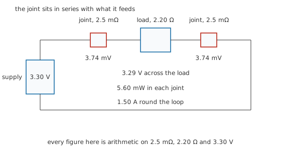
A good joint is invisible in the arithmetic, and that is the only test of it that matters.
Now let one of them go cold. The solder never wetted the pad, so the connection is a mechanical contact through an oxide film rather than an alloy bond.
Worked example — The same circuit with one cold joint
The supply is still 3.30 V and the part is still 2.20 Ω, but one joint now measures 0.80 Ω instead of 2.5 mΩ.
Current through the loop falls to 1.10 A. The bad joint keeps 0.879 V of the supply for itself and leaves 2.42 V for the part it is meant to feed.
The joint is now dissipating 0.966 W in a very small piece of metal, which is why a cold joint on a current-carrying path tends to discolour the board around it and to get worse with age rather than better.
A cracked joint behaves differently again. Where a cold joint is a poor contact, a crack is a nearly absent one: the alloy has parted, and whatever current gets across does so through however much of the two faces still touch. Put 45 Ω into the same path and the current collapses to 69.9 mA, the part sees 154 mV and does nothing at all, and the joint itself absorbs 220 mW.
None of that is what a continuity beeper reports. The beeper sounds below a threshold of its own, often somewhere near 30 Ω, and a cold joint at 0.80 Ω is 320 times the resistance of a good one while still sitting comfortably inside that band. It beeps, and so does the good joint. Continuity and diode test modes sets out what the tone carries; for joints it finds the broken ones and misses the bad ones, and only the displayed number separates the two.
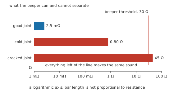
The fault the beeper catches is the one you would have found anyway.
When the problem is too much metal
The opposite fault is a bridge: solder spanning two pads that were never meant to meet. It is worth knowing how good a conductor that bridge is. Solder is a metal, with a resistivity of roughly 150 nΩ·m for a tin-lead alloy, taken here as an illustrative figure rather than a catalogue one. A bridge 2.0 mm long with a cross-section of 0.20 square millimetres works out through
at 1.5 mΩ. That is not a resistor. It is a wire.
Put one between a rail pad and its neighbour to ground, with an illustrative 90 mΩ of source resistance and 30 mΩ of track ahead of it, and the whole fault path is 121.5 mΩ. From 3.30 V that gives 27.2 A, and
puts 89.6 W out of the supply, of which 1.11 W lands in the bridge itself. Those are arithmetic on the three resistances named above, not readings taken from a bench. A real supply folds back, trips or expires instead, and which of those happens decides whether the bridge is a nuisance or a repair. Open circuits and short circuits treats the general case.
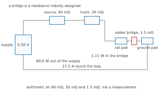
A bridge between a signal pad and ground is quieter and often harder to find: nothing gets hot, the signal is simply always low.
Professional
The iron is a thermal system too
Everything above treats the tip as a fixed temperature. A tip is really a small mass of copper with a heater behind it, and from the moment it touches a joint it loses heat faster than the heater replaces it. The front panel goes on reading 350 °C because the sensor is not at the tip face.
The depth of the sag follows from one division. Say a joint takes 8.0 J out of the tip while it is being made, illustratively. A light pencil iron whose tip has a heat capacity of 0.15 J/°C loses 53.3 °C. A heavier station tip at 0.40 J/°C loses 20.0 °C. Same joint, same energy, and nearly a factor of three between what the two tips have left to work with.
Recovery runs the other way, which is the part people get wrong. Give both irons the same illustrative heater conductance of 0.25 W/°C, and each recovers exponentially with a time constant equal to its own heat capacity divided by that conductance: 0.60 s for the light tip against 1.60 s for the heavy one. Ask each to get back within 5.0 °C of setpoint and the light tip takes 1.42 s, the heavy one 2.22 s.
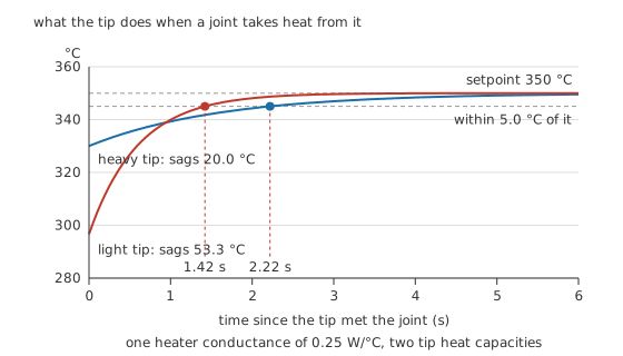
The heavy tip barely notices the joint and is slower to top itself back up; the light one dips much further and climbs back sooner.
On a single joint that trade hardly matters. On a row of them made a second apart it decides everything, because the light iron never gets its recovery time and its working temperature walks steadily downwards. That is the mechanism behind the third joint in a row being the bad one.
So the tip is chosen for the thermal mass of the joint rather than for delicacy. A ground plane or a thick lead takes its energy from somewhere, and a fine tip on that joint buys a long dwell that cooks everything nearby instead.
Lead-free work tightens each of these margins. The alloys melt about 34 °C higher, they wet more reluctantly, and a sound finished joint looks duller and grainier than a tin-lead one in a way that is normal rather than a defect. Tips wear faster, and rework is harder because everything true of the original joint is true again with less headroom.
Surface-mount work changes the method rather than the physics. Below a certain size, hand-soldering each termination stops being sensible and hot air or a full reflow profile takes over, so the temperature curve becomes something the whole assembly follows rather than something one tip delivers into one spot. SMD package sizes sets out the geometries that force the change.
Inspection is where this closes. A good joint is bright or evenly matte, concave where the alloy runs up the lead, and continuous with no visible line between fillet and pad. A cold joint is convex, dull and beaded, sitting on the pad rather than joined to it. A cracked joint often shows a fine dark ring around the lead. None of that is conclusive, which is what the arithmetic in Layer 3 is for: a multimeter reading of the voltage across a suspect joint while the circuit carries its working current settles what the eye cannot.
Common mistakes
- Heating the solder instead of the joint. Melting a bead against the tip and wiping it onto a cold pad produces something that looks finished and is not joined to anything.
- Turning the temperature up because a joint is slow. A slow joint is usually a dirty tip, a dry tip or a tip too small for the mass in front of it, and more heat makes all three worse.
- Accepting a beeper as proof. A joint several hundred times worse than it should be sits well inside the beeper's threshold and produces the same tone as a perfect one.
- Moving the part while the alloy freezes. The result is a grainy joint with a crack through it, and it will pass every test you can do with the power off.
- Using a fine conical tip on a heavy pad. The contact area is too small to move the energy, so the dwell stretches out and the heat spreads sideways into everything you were trying to protect.
Frequently asked questions
Why does my solder ball up instead of flowing?
Almost always because the surface is not clean, not hot enough, or both. Molten solder will only spread on metal it can react with, so an oxide film keeps it beaded no matter how much you add. Fresh flux and a hotter, better-tinned tip fix most cases; a badly corroded pad or lead needs mechanical cleaning first.
What temperature should I set the iron to?
Around 350 °C is a common starting point for tin-lead work and a little higher suits lead-free, but the number matters less than whether the joint itself reaches melting quickly. If the solder only flows after several seconds, the problem is the tip, the tip size or the contact, not the setting on the dial.
How do I tell a cold joint from a good one?
By eye, a good joint is smooth and concave where the alloy climbs the lead, and a cold one is a dull convex blob sitting on the pad. Appearance is only a first pass, though. The decisive test is the voltage across the joint while the circuit carries its normal current, because a joint that reads fine on an ohmmeter can still drop a large fraction of a supply under load.
How do I remove a part without wrecking the board?
Add fresh solder to the old joint first. That sounds backwards, but it brings flux in and lowers the melting point of whatever oxidised alloy is already there, which makes braid or a pump far more effective. Lift the part only once the joint is genuinely molten; pulling on a lead that is still pasty is how pads come off.
Do I have to clean the flux off afterwards?
It depends entirely on which flux it was. Some are formulated to be left in place, others are corrosive or conductive enough that leaving them causes trouble later, and the manufacturer's own documentation for the solder or the flux says which. If you do not know what you used, clean it off.