
Quick Answer
An SMD package code names a chip component's own footprint. The four digits of 0402, 0603, 0805 and 1206 give its length and width in hundredths of an inch. That one code settles the land pattern, the placement clearance, how much heat the part can shed and how much conductor it adds.
Intuition
The code is the size
A4 is not a description of a sheet of paper. It is a decision already taken about the envelope, the printer tray, the ring binder and the scanner glass. Say A4 and all of those follow without further discussion.
Surface-mount package codes work the same way, and they are more literal about it. The four digits are a measurement. The first pair is the body's length and the second is its width, both in hundredths of an inch, and a hundredth of an inch is 0.254 mm. A 1206 is twelve hundredths by six, so it comes to 3.048 mm by 1.524 mm. An 0402 is four by two: 1.016 mm by 0.508 mm. Between them sit the 0603 at 1.524 mm by 0.762 mm and the 0805 at 2.032 mm by 1.270 mm.
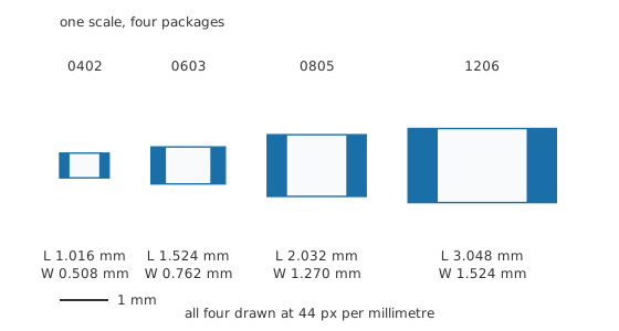
Plan view, one px-per-millimetre factor for all four; the solid bands at the ends are the solderable terminations.
Drawn side by side they sit further apart than the codes suggest. A 1206 is three times an 0402 in both directions, so it covers 9.00 times the board area — different objects sharing a catalogue page.
What the code guarantees is the family, and the family is what the stencil aperture, the placement nozzle and the rework tweezers are set up for. The manufacturer's drawing carries the actual body size and the tolerance it is held to, and those figures sit a little away from the straight inch conversion above. Resistor types and construction covers what is inside the body; this page is about the outside of it.
Practitioner
The land the part sits on
A chip resistor has no leads. A pair of metallised bands at the ends of the body is the entire electrical connection, and the solder that wets them is the entire mechanical one. The copper the board offers those bands is the land pattern, and it is never the same shape as the part.
The difference comes from three allowances, and all three of the figures below are illustrative stand-ins chosen so the arithmetic stays visible. The pad reaches past the end of the body by a toe of 0.25 mm, which is where the solder fillet forms and where an inspector looks to see whether it did. It reaches back under the part by a heel of 0.20 mm beyond the inner edge of the termination band. And it runs 0.10 mm wider than the body, so a part that lands slightly off-centre still has copper under both of its ends.
Take the 0603, with a termination band an illustrative 20 % of its own length, or 0.3048 mm. Each pad is then 0.7548 mm long and 0.862 mm wide, the pair spans 2.024 mm from outer edge to outer edge, and the bare laminate between them measures 0.5144 mm. Add the two pads up and there is 1.301 square millimetres of copper under a body of 1.161 square millimetres — more pad than part.
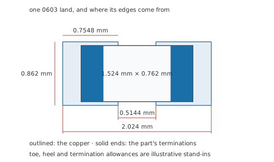
Real land patterns come from a published standard at a chosen density level; the three allowances here stand in for one.
That gap is the distance a solder bridge has to cross, and it is also the distance a hot iron has to stay clear of. Apply the same allowances to an 0402 and it closes to 0.2096 mm, narrower than most iron tips are wide. Hand assembly stops being pleasant somewhere around there, and soldering basics is where the technique lives.
The land pattern is also the thermal path. A chip resistor sheds most of its heat through its terminations into the copper rather than into the air above it, so the pads and whatever traces or planes they reach are part of the part's power rating whether the schematic admits it or not.
Engineer
What the extra millimetre buys
Rated power, and the board it was measured on
Chip resistors are sold with a power rating, and it climbs with size in the direction you would expect and by less than you would expect. Take four illustrative figures for the sizes above: 0.063 W for the 0402, 0.100 W for the 0603, 0.125 W for the 0805 and 0.250 W for the 1206. Every manufacturer publishes its own, measured on a board it specifies, and a series built for higher power will beat these in the same outline.
Body area runs 0.516, 1.161, 2.581 and 4.645 square millimetres. The 1206 therefore has 9.00 times the area of the 0402 and carries only 3.97 times the power. Per square millimetre of its own body the small part is worked harder: 122 milliwatts against 53.8, a factor of 2.27.
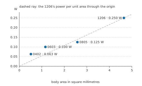
Any point above the ray is a part running hotter per unit of its own area than the 1206 does.
That is not an inconsistency in the ratings. It reflects where the heat leaves. A small chip is close to its own pads everywhere, so a larger share of its dissipation goes sideways into the copper instead of having to cross the body first. The rating is a statement about a part on a specified board, and moving the same part to a board with thinner copper or fewer vias under it makes the number smaller without anybody changing the part.
From watts to amps
Read backwards at one fixed resistance, a power rating becomes a current limit, and current is usually what a designer actually has in hand. At 100 Ω the four sizes meet their ratings at 25.1 mA, 31.6 mA, 35.4 mA and 50.0 mA.
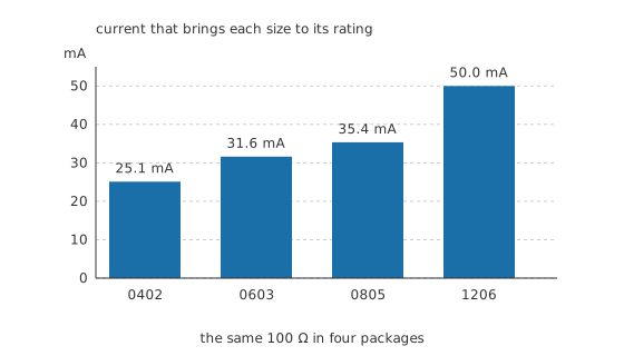
Nine times the area buys twice the current, because the rating enters under a square root.
Worked example — The current picks the package
A 100 Ω resistor sits in a path carrying 42 mA. Its dissipation is 0.176 W.
That settles three of the four sizes at a stroke. The 0402's illustrative 0.063 W is nowhere near it and the 0603's 0.100 W is short, while the 0805 at 0.125 W would be asked for 141 % of its rating. Only the 1206, at 0.250 W, has anything left: 1.42 times the dissipation, before any allowance for a warm box.
Those margins shrink again once the box warms up, because a rating is quoted at some stated ambient and falls above it. Power ratings and derating works that through and is the right place for the curve.
One limit does not follow size the same way. Each part also carries a maximum working voltage, set by how far apart its two terminations sit rather than by how much heat it can lose, and on high-value resistors that limit binds long before the power rating does. No amount of dissipation headroom rescues a part that is too short for the voltage across it.
Professional
Board area, lead length and a naming collision
Forty parts, four sizes
One part's footprint is not what sets a board's size. The placement cell does: the land pattern plus enough room around it for the assembly process to work in. Give each part an illustrative 0.25 mm of clearance on every side of its pads and count 40 of them.
The totals come to 89.3, 137.5, 226.8 and 343.9 square millimetres. Dropping from the largest to the smallest saves 254.6 square millimetres, a factor of 3.85.
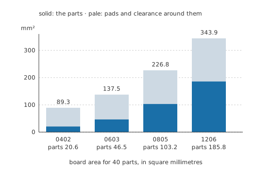
Below the line in each bar is the part; above it is everything the part needs around it.
The split inside each bar matters more than the totals do. Forty 0402 bodies come to 20.6 square millimetres, which is 23.1 % of the area they occupy, while the 1206's bodies are 54.0 % of theirs. Shrink the part far enough and you stop paying for parts and start paying for the space between them. Getting past that takes a tighter assembly process rather than a smaller chip.
The conductor the part adds
Between a board trace and the resistive element itself there is always some conductor, and it has inductance. On a chip that conductor is the two termination bands. On a through-hole part it is two leads, and the difference is not subtle. At an illustrative 1.0 nanohenries per millimetre, an 0402 with 0.4064 mm of termination contributes 0.4064 nH and a 1206 with 1.2192 mm contributes 1.2192 nH, while a through-hole part with 5.0 mm of lead at each end, 10.0 mm altogether, contributes 10.0 nH. That is 24.6 times the 0402's.
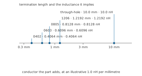
The figure per millimetre is a stated stand-in rather than a measurement; the ranking survives whatever real number replaces it.
At audio and at ordinary logic speeds nobody notices. At the edge rates around a modern digital supply rail the same nanohenries decide whether a decoupling capacitor does its job at all, which is one reason the parts nearest a fast chip are small ones on short traces rather than large ones on convenient ones.
Two series, the same four digits
Everything above uses the imperial series. A metric series names the same parts by their millimetre dimensions, so these four are also called 1005, 1608, 2012 and 3216. The two systems do not convert into one another digit for digit; each belongs to its own set of drawings.
The trap is that a few names appear in both. A part called 0603 in the metric series is six tenths of a millimetre by three tenths, which the imperial series calls an 0201, a chip smaller than a grain of rice and a different component in every practical sense. A bill of materials that does not say which series it means has not specified the part.
The smallest packages also stop carrying a marking. There is nowhere on an 0402 to print anything, so its value lives on the reel label and in the assembly file and nowhere on the part itself. SMD resistor codes covers what the larger sizes print and how to read it.
Through-hole survives, and the reasons are mostly mechanical. A connector that will meet a plug several hundred times wants that force carried by plated barrels rather than by solder on a surface. A part that gets swapped in service is easier to swap with leads. High-voltage spacing is easier to buy in the third dimension. A part heavy enough to need support is often through-hole because nothing else holds it down. Almost everything else on a current board is a chip, and that chip is an 0402 or an 0603 unless somebody made a specific argument for more.
Common mistakes
- Reading a package code as a specification — it fixes the outline and nothing else. Two 0805 resistors can differ in tolerance, temperature coefficient, power rating and working voltage, all in the same body.
- Treating the power rating as a property of the part alone — it is quoted against a specified test board, and the copper attached to the pads carries most of the heat away.
- Drawing a land pattern to the body's own dimensions — pads are longer and wider than the part on purpose, and a pad that matches the outline leaves no fillet to form and nothing to inspect.
- Mixing the imperial and metric series in one document — the same four digits name two different parts, and the smaller one will go on the board without complaining.
- Shrinking the package to shrink the board — below a certain size the clearance around the parts dominates the total, and the assembly process rather than the chip sets the pitch.
Frequently asked questions
What do the numbers in an SMD package code mean?
Length and width, in hundredths of an inch, in that order. An 0805 is eight hundredths long by five hundredths wide. Every other property of the part, including its resistance and its power rating, has to come from somewhere else.
Is an 0603 the same size everywhere?
No, and this catches people. The imperial 0603 is a chip about a millimetre and a half long. A metric 0603 is far smaller and matches what the imperial series calls an 0201. Check which series a drawing, a reel label or a bill of materials is using before you order.
Can I hand-solder an 0402?
Yes, with a fine tip, good flux, fine solder and tweezers you trust, and it is a great deal easier under magnification. Most people find 0805 comfortable, 0603 workable and 0402 a job they would rather do with a stencil and hot air.
Does a bigger package always handle more power?
Within one series, yes. Across series, no. A high-power 0805 from one family can outrank an ordinary 1206 from another, because the rating depends on the element, the terminations and the test board as well as the outline. Read the number rather than inferring it from the size.
Why do the smallest chip resistors have no markings?
There is no room to print one. On an 0402 the whole top surface is smaller than a typical printed character needs, so the value stays on the reel and in the assembly data. It also means a loose part off the bench floor is unidentifiable without a meter.
When is a through-hole part still the right choice?
When something mechanical is happening. Connectors that take repeated insertion, parts that will be replaced in service, components heavy enough to need their own support, and anything needing clearance that is easier to find vertically than across a board surface.