
Quick Answer
Resistor types are the constructions used to build a resistance: carbon composition, thick film, metal film, thin film and wirewound. Each holds the same marked value, and each holds it differently. Construction decides tolerance, temperature drift, noise, pulse handling, and how high in frequency the part still behaves as a resistance.
Intuition
The same job in four materials
A spanner in chrome-vanadium steel, one in aluminium bronze and one in nylon all turn the same nut. Same tool, same job. The material decides where each belongs: the steel one on an engine, the bronze one where a spark would be dangerous, the nylon one on a plated fitting nobody wants scratched. Which is best is not a question you can answer without knowing where.
Resistors are sold the same way. The resistor is one component with one job, and catalogues offer it in several constructions that all meet the same marked value. A 68 Ω carbon composition part, a thick film chip, a metal film part and a wirewound all read sixty-eight ohms on a bench meter in a cool room. They stop agreeing the moment anything else about the room changes.
Warm all four by 60 °C and they separate. The carbon composition part moves 1.02 Ω. The metal film part moves 61.2 mΩ. Neither is faulty and neither has left its specification — they are made of different things.
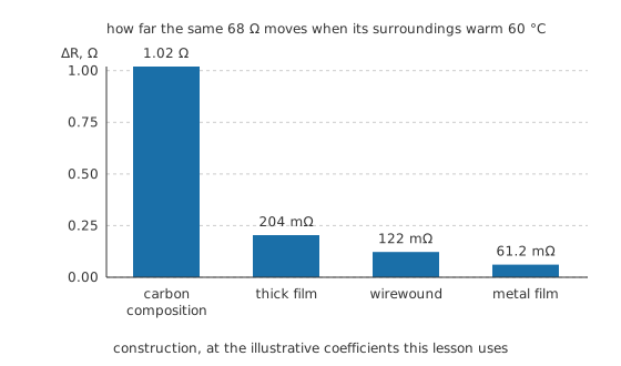
One resistance, four constructions, one temperature rise.
What differs is the element, the piece of material the current actually crosses, and the shape it has been cut into. A film part is a thin coat on a ceramic rod, trimmed until it reads right. A wirewound is a length of resistance alloy on a former. A carbon composition part is a moulded slug of carbon and binder with a lead at each end. Everything else on this page is downstream of those differences.
Practitioner
What each construction is for
Tolerance and temperature coefficient separate the constructions before anything else does. Tolerance says how close to the marked value the part starts; the temperature coefficient, quoted in parts per million per degree, says how far it wanders once the room stops cooperating. Resistor tolerance and precision takes the first apart on its own.
Carbon composition runs 5.0 % and 250 ppm/°C. Thick film, the chip resistor on nearly every board made this decade, runs 1.0 % and 50 ppm/°C. Metal film: 0.10 % and 15 ppm/°C. Wirewound: 0.50 % and 30 ppm/°C. Those four pairs are illustrative stand-ins carried through the rest of the lesson, picked to show the spread between constructions. A manufacturer's own table is the only place the real ones live, and the spread within one construction is wide enough that a grade always has to be read rather than assumed.
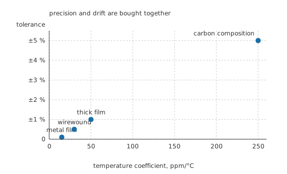
The two properties improve together; the bottom-right corner of this plot is empty.
Plotted against each other the four fall close to a line, and the reason is not a coincidence of pricing. Both properties come from the same decision: whether the element is a continuous metal or a composite of grains pressed together. Metal gives you a stable, repeatable resistivity you can trim against; a composite gives you neither. Wirewound is the odd one out only in that it buys stability with a shape that costs you elsewhere, which Layer 3 gets to.
Worked example — Two parts, one warm afternoon
Two 68 Ω resistors sit beside each other in an enclosure that settles 60 °C above the bench temperature they were measured at. One is carbon composition at an illustrative 250 ppm/°C, the other metal film at 15 ppm/°C.
The carbon composition part ends at 69.02 Ω, the metal film part at 68.06 Ω. They went in matched to the resolution of any meter on the bench and came out 959 mΩ apart. In a divider that sets a comparator threshold, that gap is a design error found in the field. In a pull-up, nobody will ever know it happened.
The middle two land where you would guess: thick film shifts 204 mΩ over the same rise and wirewound 122 mΩ.
Feedback dividers, references and anything whose ratio has to survive a warm enclosure get film with a low coefficient. General wiring, pull-ups and decoupling neighbours get thick film chip, because it is cheap, small and adequate (SMD package sizes). Serious continuous power gets wirewound, whose element can be made fat and whose ceramic body is built to run hot (power ratings and derating). Carbon composition survives in the places that value a bulk element over a precise one.
Engineer
Material, shape and what follows from both
How much element a value needs
A resistance is a material property multiplied by a shape. Read the same relation backwards and it tells you how much element a given value costs, and the answer is wildly different for a film and for a wire.
Take an illustrative film resistivity of 0.75 µΩ·m, laid down as a track 0.25 mm wide and 0.30 µm thick. Reaching 68 Ω takes 6.80 mm of that track, barely more than the 5.0 mm rod it is printed on. The helical groove that trims the film to value therefore wraps 0.73 of a turn and stops. Higher values need many turns; this one does not.
Now the wire. A resistance alloy at an illustrative 1.10 µΩ·m, drawn to 0.050 mm in diameter, needs 121 mm for the same 68 Ω. That is 17.85 times the film's path, and on a 2.0 mm former it comes to 19.3 turns. Both resistivities above are illustrative stand-ins, not figures for a named alloy, and the point survives whichever real numbers you substitute: metals that make good resistance wire are still far better conductors than a resistive film, so a wire element has to be long.
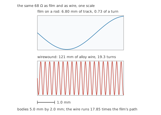
Both drawn to one px-per-millimetre factor, on the same body.
A winding is a coil
Those 19.3 turns do a second job nobody ordered, and the winding cannot avoid doing it. Give the part an illustrative 1.8 µH in series with its resistance and the consequences are arithmetic:
At 1.00 MHz the reactance has reached 11.3 Ω, and the magnitude the circuit meets is 68.9 Ω rather than 68 Ω. Push on and the reactance overtakes the resistance at 6.01 MHz, where the part measures 96.2 Ω — half as much again as the number stamped on its body. Above that it is mostly a coil. Impedance sets out the general case.
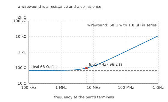
The dashed line is the ideal part; the curve is the same value with its winding attached.
Manufacturers do fight this. Bifilar and Ayrton-Perry windings send the current back along its own path so the two halves cancel most of the field, and both cost money and space for the privilege. They reduce the inductance rather than removing it.
The noise floor and what sits on it
Every resistance generates a noise voltage that depends on its value, its temperature and the bandwidth you look through, and on nothing else at all:
At 1.00 MΩ, 298.15 K and a bandwidth of 10.0 kHz, that floor is 12.8 µV. It is the same figure for a film part, a wirewound and a carbon composition part of that value, because the mechanism is thermal agitation inside the resistance itself and not anything about how the resistance was built. Noise in circuits treats the floor properly.
What construction changes is what piles on top. A composite element carries its current through a mass of touching grains, and the contacts between them are not perfectly steady. The result is excess noise: it appears only when a current flows, it grows with that current, and it sits at low frequencies, which is where it does the most damage in audio and in slow measurement. At an illustrative 8.00 times the floor, the carbon composition part reads 103 µV against the film part's 12.8 µV. That multiple is a stand-in to show the shape of the problem rather than a specification for anything. Film parts are quieter because the element is continuous metal, and thin film is quieter than thick.
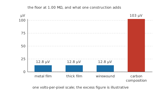
Three of these bars are the same height because the floor does not care what the part is made of.
The temperature coefficient has the same root. A metal's resistivity climbs with temperature in a fairly linear and fairly repeatable way (temperature effects on resistance), so a film of that metal inherits a coefficient a manufacturer can specify and hold. A composite has two mechanisms pulling against each other, the grains conducting like a metal and the contacts between them not doing so, and the sum is large, curved and not held tightly by anyone.
Professional
Where the resistor stops being a resistance
Every real part is a resistance with an inductance in series and a capacitance across it. The values are small, the model holds a long way, and then it stops holding.
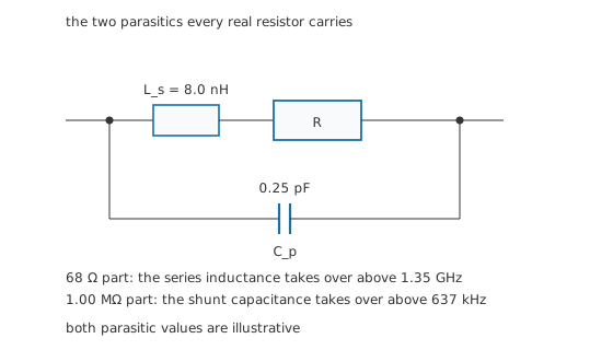
Which end of the model expires first depends on the resistance between the two parasitics.
The illustrative values here are 8.0 nH of series inductance and 0.25 pF across the body, figures of the right order for a small axial part rather than a measurement of one. Which parasitic bites depends entirely on the resistance sitting between them. For the 68 Ω part it is the inductance, and it costs nothing until 1.35 GHz. For a 1.00 MΩ part it is the capacitance, and that starts to matter at 637 kHz — six hundred and thirty-seven kilohertz is not a high frequency, and a designer who put a megohm in a signal path expecting a resistor has quietly built a low-pass filter instead.
Pulses ask a different question again, and the answer runs the opposite way to precision. A carbon composition element takes its energy into the whole volume of the slug. A film element takes the same energy into a coat a fraction of a micrometre thick, wound into a narrow spiral — the hot spot has nowhere to spread. That is why carbon composition and bulk-element parts still get specified into surge paths and crowbar circuits long after they lost every other argument, and why a film part rated comfortably for average power can still be destroyed by a short pulse well inside that rating. Resistor failure modes follows what happens next.
Environment sorts them too. Thick film terminations that contain silver are attacked in sulfur-rich air, which is a slow open circuit rather than a dramatic one. Moisture reaches a film through a damaged coating and shifts it. A wirewound part on a ceramic former is physically the toughest of the four and the most awkward to fit. None of that appears in the resistance figure, and all of it appears in the returns.
So the modern board is nearly all thick film chip, and the exceptions are where they have to be. Precision and low drift go to metal or thin film. Continuous heat goes to wirewound or metal oxide. Current sensing goes to a purpose-built metal element with four terminals, so that lead and joint resistance stay out of the measurement (current-sense resistors). Anything adjustable is the same element question with a contact dragged across it (potentiometers and trimmers).
Common mistakes
- Reading a temperature coefficient as if it were a tolerance — tolerance is where the part starts, the coefficient is where it goes. A part inside tolerance on the bench can be well outside your error budget in a warm box.
- Putting a wirewound in a fast path because its power rating looked generous — its element is a coil, and a fast edge meets the inductance long before it meets the resistance. Power handling and frequency behaviour are separate purchases.
- Treating "film" as one thing — thick film and thin film differ in tolerance, drift, noise and price by roughly the same distance that separates thick film from carbon composition. The word alone specifies nothing.
- Expecting a quieter construction to lower the thermal noise — it cannot. The floor is set by resistance, temperature and bandwidth. Construction only decides how much excess noise is stacked on it, and lowering the resistance is what moves the floor.
- Choosing carbon composition for a signal path because it is old and cheap — old and cheap is true, but it is also the noisiest and the least stable of the four. Its remaining case is pulses, not audio.
Frequently asked questions
What is the difference between thick film and thin film resistors?
Thickness, and everything that follows from it. A thick film element is a paste printed and fired onto a substrate, tens of micrometres deep and grainy; a thin film element is metal deposited a fraction of a micrometre deep and continuous. Thin film gives tighter tolerance, a lower temperature coefficient and less noise, and it costs more.
Are wirewound resistors bad at high frequency?
Yes, and unavoidably so. The element is a length of wire wound around a former, which is the definition of an inductor. Bifilar and Ayrton-Perry windings cancel most of the field and reduce the effect, but a wirewound part is the wrong choice wherever the signal is fast.
Do carbon composition resistors still have a use?
In surge and pulse paths, yes. The element is a solid slug, so a short overload spreads its energy through the whole body instead of concentrating it in a thin trimmed film. They are also still bought for repairs and for guitar amplifiers, where the noise is part of what people are after.
Which resistor type is best for precision?
Thin film for the tightest tolerance and lowest drift, metal film a step behind it and much cheaper, and wirewound where stability matters more than speed. If what you need is a stable ratio rather than a stable value, matched parts made together on one substrate beat any two loose parts of the same grade.
Can I substitute a metal film resistor for a carbon film one of the same value and rating?
Usually, and usually the result is better. Watch two cases: a pulse or surge path, where the film's thin element is the weaker part, and a circuit where somebody was relying on the older part's noise or drift. Physical size and lead spacing still have to fit.