

Quick Answer
The resistance of most materials changes with temperature. In metals it rises, because the vibrating lattice scatters the moving charge more often. In semiconductors and insulators it falls, because heat creates additional charge carriers. The rate of change is called the temperature coefficient of resistance.
Intuition
A crowded corridor at rush hour
Walking down an empty corridor is easy. Walking down the same corridor while everyone in it is fidgeting and waving their arms takes longer, and you collide more often. The corridor has kept its width and the crowd its size; all that has gone up is the movement inside it.
Metals behave that way when they get hot. The atoms sit in a regular arrangement, and the electrons that carry the current thread their way past them. Heat makes those atoms vibrate more vigorously about their fixed positions, so the electrons meet them more often and drift more slowly for the same push. The metal's resistance goes up.
The effect is large enough to change what a circuit does. A copper motor winding running hot has meaningfully more resistance than the same winding on a bench in a cool room, and so does a lamp filament, a heating element, or a long cable on a summer afternoon. Anyone who has measured a heater's element cold, calculated the power it should take, and then found the appliance drawing less than expected has met this directly.
Semiconductors go the other way, for a reason that has little to do with jostling. What limits them is the supply of carriers: at low temperature almost no electrons are free to move at all. Heating one liberates more of them, and the carriers gained matter far more than the extra jostling costs. A semiconductor's resistance therefore falls as it warms, often steeply.
That difference in sign has a practical payoff. A material whose resistance changes predictably with temperature is a thermometer, and a great many temperature sensors are exactly that: a carefully specified piece of metal or semiconductor whose resistance you measure.
Practitioner
The linear model
Over a moderate range, a metal's resistance changes almost proportionally with temperature, so a single coefficient describes it:
The coefficient α is quoted per degree Celsius, at a stated reference temperature — almost always 20 °C. Copper's is about 0.00393 /°C, near enough to four parts in a thousand per degree for mental arithmetic.
Worked example — A motor winding at working temperature
A copper winding measures 10 Ω at room temperature. In service it runs 80 °C hotter.
Applying the coefficient gives its hot resistance: 13.1 Ω, an increase of 31.4 %.
An error of that size propagates through the rest of the design. Working from the cold figure predicts more current than the machine draws, and with it more torque and more dissipation, so the supply and the protection end up sized against numbers the machine never reaches.
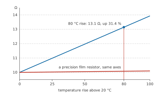
The sign of the coefficient gives the material its label. A resistance that rises with temperature has a positive temperature coefficient — metals, and the PTC devices built deliberately to exaggerate the effect. A resistance that falls has a negative coefficient: semiconductors, carbon, and NTC thermistors. Some alloys are formulated to sit almost at zero.
Turned around, the effect becomes a measurement. The resistance of a winding gives its average temperature with no sensor anywhere inside it, which is how motors and transformers are temperature-tested, and the resistance of a platinum element is what an industrial thermometer actually reads — see RTDs.
Trusting a cold measurement as though it were a hot one is where it catches people out. A cold filament lamp has a much lower resistance than a hot one, so it draws a large inrush current at switch-on, and a heating element does the same. A current-sense resistor that drifts with its own self-heating reports a current wrong by the amount of the drift, and the error grows with the current being measured — which is exactly when accuracy matters most.
Published resistivity figures are 20 °C figures. Any calculation of cable resistance, voltage drop or dissipation that starts from a table value is a room-temperature calculation, and the answer for a hot conductor is larger.
Engineer
Running the model backwards, and where it stops working
The relationship works in either direction. A coefficient and a cold reading give the hot resistance; the same coefficient and two readings give the temperature rise between them.
Worked example — Taking a winding's temperature with an ohmmeter
A winding measures 10 Ω at an ambient of 20 °C. After running under load it measures 12 Ω.
Working the coefficient backwards from the resistance ratio gives the rise: 50.9 °C. Adding the ambient gives the winding's average temperature: 70.9 °C.
That word average carries a warning with it. The method reports the mean temperature of the whole conductor, while insulation fails at the hottest spot, which is invariably higher. So the standard way of establishing a machine's temperature rise is also a method that systematically underestimates the worst place in it.
Underneath the corridor image, the two families of material differ in what temperature is free to change. A metal has a fixed number of carriers, set by its structure, so heat can alter only how often they scatter; resistivity follows the scattering rate, which rises roughly linearly with absolute temperature over ordinary ranges. A semiconductor scatters more when heated as well, but its carrier population rises exponentially at the same time, and the exponential wins comfortably.
The linear model comes with a range attached to it. Over a wide span metals need a quadratic term, and at very low temperatures resistivity flattens out to a residual value set by impurities and defects rather than by vibration, with some metals losing their resistance entirely below a critical temperature. Semiconductors are exponential from the start, so for them the linear coefficient is a local slope rather than a description — which is why thermistors are specified by a curve or by a beta parameter rather than by an α.
Measuring a resistance also warms it. Any such measurement passes a current, that current dissipates power in the element, and the element ends up hotter for having been read. In a thermistor with a small thermal mass the effect is a real error, quantified as a dissipation constant in milliwatts per degree, and it is the reason sensor excitation currents are kept small or pulsed.
The sign decides whether heating settles down or escalates. A metal that heats draws less current, which reduces the heating, so the loop closes on itself and stabilises. A semiconductor that heats conducts more, dissipates more and heats further, which is thermal runaway, and it sits behind a whole family of destructive failures. Devices that share current in parallel are safe when the coefficient is positive and need deliberate ballasting when it is negative.
Drift can also be designed against directly. A component with the opposite coefficient placed in the same circuit cancels the drift to first order, and alloys such as manganin and constantan exist because their coefficients are near zero over a useful range — which is why precision shunts and strain-gauge bridges use them rather than copper.
Professional
Tempco as a specification
Component tempco is quoted in parts per million per degree, because the changes that matter in precision work are far smaller than a percent. A 10 kΩ resistor with a coefficient of 0.0001 /°C — a hundred parts per million per degree — moves to 10.05 kΩ over a 50 °C rise, a change of 0.5 %. That is larger than the tolerance of a precision part, so in any circuit that warms up, tempco rather than initial tolerance is what limits accuracy. Resistor tolerance makes the same point from the other direction.
Ratios survive far better than absolute values do. Two resistors on the same die share a temperature and a coefficient, and the ratio between them holds even while each one drifts. Integrated circuits are designed around ratios wherever they can be, matched resistor networks exist as products, and a divider built from two parts of the same type will outperform one built from whatever was in the drawer.
Temperature sensors are this effect made deliberate. A platinum RTD uses a metal whose positive coefficient is stable, repeatable and close to linear, standardised in IEC 60751 so that any manufacturer's element reads the same. An NTC thermistor uses a semiconductor instead, for a much larger negative coefficient that is strongly non-linear: more sensitive and cheaper, at the cost of linearity. Choosing between them trades accuracy and range against sensitivity and cost.
PTC devices are built for a positive coefficient so sharp that it works as a switch. A polymeric resettable fuse is nearly a plain conductor until self-heating pushes it past a transition, at which point its resistance climbs by orders of magnitude and the device becomes an effective open circuit — see current limiting. It recovers when it cools, which suits repeated overloads and rules it out wherever protection has to be fast and precise.
Inrush current is a temperature-coefficient effect, and so is the usual cure for it. A cold filament or heating element draws heavily until it warms. An NTC thermistor in series runs the other way — high resistance when cold to limit the surge, low once warmed by the load current — which is the standard soft-start for capacitor-input supplies. It also means the protection is absent if the equipment is switched off and straight back on before the thermistor has cooled.
At this point thermal design and electrical design stop being separable. Resistance sets dissipation, dissipation sets temperature, and temperature sets resistance. In a copper conductor that loop converges; in a semiconductor it may not. Any current-carrying design sitting near the edge of its thermal envelope has to be checked at the hot end of its operating range rather than at room temperature — which is what the derating curves in power dissipation and on every heatsink datasheet exist for.
Common mistakes
- Using cold resistance for a hot component — motor windings, filaments and heating elements all measure much lower on a bench than in operation, and the calculated current comes out too high.
- Applying the linear model outside its range — it is a local approximation around a reference temperature. Wide spans need higher-order terms, and semiconductors are not linear at all.
- Ignoring self-heating in a sensor — the measuring current warms the element it is measuring. Keep excitation small or pulse it.
- Paralleling devices with a negative coefficient without ballast — the hottest one takes more current, heats further and takes more still. Positive-coefficient devices share naturally; negative-coefficient ones do not.
- Specifying tolerance and forgetting tempco — over a fifty-degree rise, a hundred parts per million per degree exceeds the initial tolerance of a precision part.
- Reading a resistance-derived winding temperature as the hot-spot temperature — it is an average, and insulation fails at the hottest point, which is always higher.
Frequently asked questions
Why does the resistance of a metal increase with temperature?
Heat makes the lattice atoms vibrate more, so the conduction electrons scatter more often and drift more slowly for the same applied field. The number of carriers does not change, only how freely they move.
Why does a semiconductor behave the opposite way?
Because heating liberates additional charge carriers across its energy gap. That gain outweighs the extra scattering, so conductivity rises and resistance falls, often steeply.
What is the temperature coefficient of resistance?
The fractional change in resistance per degree of temperature change, quoted at a reference temperature. Copper's is roughly four parts in a thousand per degree; precision resistors are specified in parts per million per degree.
How can resistance be used to measure temperature?
By measuring an element's resistance and inverting a known relationship. Platinum RTDs use a standardised, nearly linear metal characteristic; thermistors use a much more sensitive but non-linear semiconductor one.
What is thermal runaway?
A self-reinforcing loop where a device with a negative temperature coefficient heats, conducts more, dissipates more and heats further. It is a destructive failure mode for semiconductors and for parallel devices without ballasting.
Knowledge check
A copper winding measures 10 Ω cold and runs 80 °C hotter in service. What is its hot resistance? (Show answer)
A winding measuring 10 Ω at an ambient of 20 °C reads 12 Ω after running. How hot is it? (Show answer)
A 10 kΩ precision resistor has a coefficient of 0.0001 /°C. How much does it move over a 50 °C rise? (Show answer)
Why does an incandescent lamp draw a large surge of current at switch-on? (Show answer)
Why do parallel semiconductor devices need ballasting while parallel resistors do not? (Show answer)
References
- CRC Press, CRC Handbook of Chemistry and Physics — temperature coefficient of resistivity for copper at 20 °C, the figure used in the worked examples.
- IEC 60751, Industrial platinum resistance thermometers and platinum temperature sensors — the standardised platinum characteristic referred to in Layer 4.