
Quick Answer
A thermistor is a resistor built so that its resistance changes sharply with temperature. NTC types fall as they warm and PTC types rise. The change is large, repeatable and thoroughly non-linear, which makes a thermistor a sensitive thermometer that needs either a model or a lookup table before it can be read.
Intuition
An old radio dial
On an old analogue radio the stations are not evenly spread along the dial. At one end they crowd together, three of them inside a millimetre of travel; at the other end the same millimetre buys you almost nothing. The dial is perfectly repeatable and perfectly useless as a ruler.
A thermistor answers temperature the way that dial answers frequency. It is a small bead or chip of semiconducting oxide with a connection at each end, and its resistance responds to heat far harder than any ordinary resistor does. Warm it and the resistance collapses. Cool it and the resistance climbs. That is a negative temperature coefficient, and NTC is what most people mean when they say thermistor at all.
The size of the effect is what makes the part worth having. Take an NTC marked 10.0 kΩ at 25 °C. Cool it to 0 °C and it measures 33.6 kΩ; warm it to 60 °C and it measures 2.49 kΩ. A precision film resistor crossing the same sixty degrees moves by a fraction of one per cent. Temperature effects on resistance covers why a semiconductor runs the opposite way to a metal; what matters here is how far it runs, and how unevenly.
Positive-coefficient parts exist as well, and they are not one family. Some are formulated for a modest, nearly straight rise: a part also marked 10.0 kΩ at the same reference point, with a coefficient of 0.00800 /°C, would go from 8.00 kΩ at the cold end of that window to 12.8 kΩ at the hot end. Others are built to do almost nothing until a threshold and then climb by orders of magnitude, which is a switch rather than a sensor. Layer 4 comes back to those.
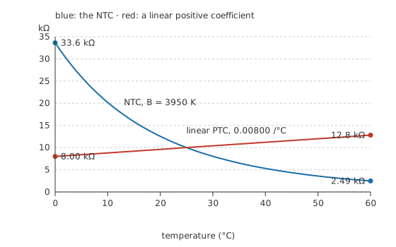
Both parts are marked the same at room temperature. One of them stays close to that mark.
Practitioner
Fitting a curve a coefficient cannot describe
A metal, or a positive-coefficient part formulated to imitate one, is described adequately by a single number: the fractional change per degree.
That is the model behind the gently rising line on the first figure, and it works there because the line really is nearly straight. Applied to the NTC it falls apart within a few degrees, because the NTC is not a line being approximated — it is an exponential.
The description that fits is the beta model, which anchors the part at one known point and lets an exponent in reciprocal absolute temperature carry it everywhere else.
B has units of kelvin and typically sits in the low thousands; the part in this lesson carries 3950 K. Note what the model needs: a resistance at a reference temperature, and one exponent. Both come from the manufacturer, and both are fitted from two measured points rather than derived from anything. That is worth remembering when Layer 4 asks how far the model can be trusted.
Turning resistance into something a circuit can read usually means a divider. Put the thermistor in the upper arm, a fixed resistor in the lower arm, and read the junction.
Worked example — Does the output fit the converter's input span?
An NTC of 10.0 kΩ at 25 °C, with 3950 K, sits above a fixed 10.0 kΩ and the pair is fed from 3.30 V. The window to be covered runs from 0 °C to 60 °C.
The beta model puts the thermistor at 33.6 kΩ at the cold end and 2.49 kΩ at the hot end, a ratio of 13.5 across the window.
The divider turns those into 0.757 V and 2.64 V, with the two arms matching exactly at 1.65 V in the middle. The output moves by 1.89 V, which is 57.2 % of the supply.
Slightly over half the converter's span, used by a sensor that never approaches either rail, is a comfortable place to be. Enlarging the swing means a different fixed resistor, and that choice buys range at one end by giving it up at the other.
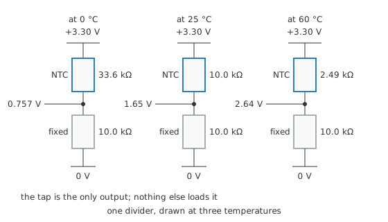
The same divider drawn at three temperatures. Only the upper arm changes.
Choosing the fixed resistor equal to the thermistor's resistance at the middle of the window is the usual starting point, and it is a compromise rather than a rule. Sharing the supply with the sensor also means the reading inherits the supply's noise and drift, which is why converters that measure this kind of divider are often referenced to the same rail that feeds it. That cancellation is the same trick the Wheatstone bridge uses, arrived at from a different direction.
Engineer
The straight line hiding in the curve
An exponential in 1/T has a consequence the resistance-against-temperature plot hides completely: take the logarithm of the resistance, plot it against the reciprocal of absolute temperature, and the curve becomes a straight line. Its slope is B.
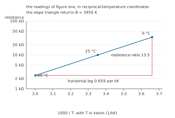
Same part, same three readings, different coordinates. The triangle is drawn, not asserted.
Drawing the triangle across the working window recovers 3950 K, which is the figure the model started from. That is not a coincidence, and it is not circular either: it is the recipe. Measure a part's resistance at two known temperatures, take the ratio, divide the logarithm of that ratio by the difference of the reciprocal temperatures, and B falls out. Every published B for every NTC was obtained that way, at two temperatures the manufacturer chose and states.
Plotting a sensor in the coordinates that straighten it is a habit worth acquiring, because a straight line makes departures visible. A real part measured at six temperatures and plotted this way shows its curvature as a gentle bow away from the best-fit line, and the size of that bow is the honest error of the two-point model.
The dial is still crowded
Straightening the plot does not straighten the part. Over the degree above 0 °C the resistance falls by 5.14 %/°C; over the degree above 25 °C it falls by 4.33 %/°C; over the degree above 60 °C by 3.49 %/°C. Sensitivity is highest where the part is coldest, and it fades steadily as the part warms.
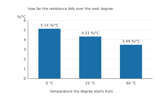
These are percentages of very different resistances. In ohms the gap is far wider.
Each percentage is taken of a very different resistance, and that is what the divider is quietly fixing. In ohms per degree, the thermistor is 19.9 times more responsive at the cold end of the window than at the hot end. Run the same part through the divider and the output voltage's slope varies by only 1.69 to one across the same span. The fixed resistor has not made the sensor linear. It has compressed a twenty-to-one variation in slope into something a converter can live with, and a lookup table or a software fit still has to handle the rest.
Reading it warms it
Any resistance measurement pushes a current through the thing being measured, and that current turns into heat inside it. On a bead with almost no thermal mass this is not a rounding error. Manufacturers publish it as a dissipation constant in milliwatts per degree, and the reading error is simply the dissipation divided by that constant.
At 3.30 V, with the thermistor at its coldest and largest, the divider draws 75.7 µA. That puts 192 µW into the thermistor, and against an illustrative dissipation constant of 2.0 mW/°C for a small bead in still air, it warms itself by 0.096 °C. Halve the excitation to 1.65 V and the dissipation falls to 48.1 µW and the error to 0.024 °C. Double it to 6.60 V and the same divider puts 770 µW into the bead and reports a temperature 0.385 °C too high.
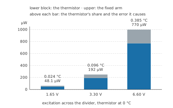
Signal grows with excitation and error grows with its square, so the trade turns against you quickly.
The error scales as the square of the excitation while the signal scales only in proportion, so raising the excitation to fight noise is a losing move past a certain point. It is also an error that hides. It is repeatable and smooth, so it reads as a slightly wrong calibration rather than as noise. The usual defences are a smaller excitation, a pulsed one that lets the bead cool between readings, or a dissipation constant chosen for the mounting rather than for still air, because a bead clamped to metal sheds heat far better than one dangling in air.
Professional
What the beta model does not promise
A pair of measured points and one exponent is a small amount of information to describe a part across a hundred degrees, and the model behaves accordingly. Inside a modest window around the reference temperature it is close. Widen the span and the error grows — the real characteristic is bowed, and a fit anchored at two points can only be exact at those two points. Manufacturers respond by publishing several values of B for different temperature pairs, which is a plain admission that one exponent does not cover the range.
Where the two-point model is not good enough, the usual replacement is the Steinhart–Hart equation: a three-term fit in the logarithm of resistance, calibrated at three temperatures instead of two, which tracks a real part across a wide span far more closely. It costs three coefficients in firmware and three calibration points on the bench, and for most work below that standard a lookup table with interpolation between entries is simpler and just as good.
The exponent has a tolerance too
A thermistor's specification carries two independent errors, and they behave differently. The resistance at the reference temperature has a tolerance, which shifts the whole curve up or down. B has its own tolerance, which tilts it. A part that is exact at its reference point can still be several degrees out at the ends of a wide window, purely from the exponent. Parts sold as interchangeable are graded on both, and specified as a maximum error in degrees over a stated range rather than as a percentage of resistance, because degrees are what the user actually cares about. Resistor tolerance sets out the general shape of this; the thermistor's version has the second, angular term that a plain resistor does not.
How fine a step the converter takes
The other limit is the instrument. A converter divides its input span into a fixed number of steps.
A 4096-step converter across 3.30 V resolves 806 µV. Because the divider's output slope is steeper at the cold end, that one step is worth 0.026 °C at 0 °C and 0.044 °C at 60 °C. The crowded end of the dial is the end the converter reads best, and the two figures differ by less than a factor of two only because the divider compressed them.
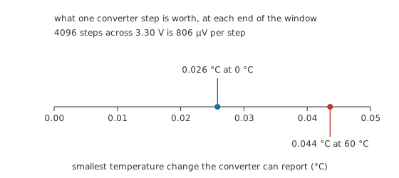
The converter's step is fixed. What it is worth in degrees is not.
Resolution is not accuracy, and accuracy, resolution and measurement error keeps the two apart properly.
Inrush limiters and switching PTCs
Not every thermistor is a thermometer. An NTC placed in series with a mains-input supply is high in resistance while cold, which limits the surge as the reservoir capacitor charges, and low once the load current has warmed it. That is a deliberate use of self-heating rather than an error, and it comes with a caveat: the part has to cool before it protects anything again, so equipment switched off and straight back on gets no protection at all. Such a limiter sits at line potential and runs hot enough to burn, which is a matter for electrical safety rather than for a bench measurement like the one this lesson works through.
Switching PTC parts push the same idea further. A polymeric device is nearly a plain conductor until self-heating carries it past a transition, at which point its resistance climbs steeply and it holds itself there on the leakage current alone; resettable fuses and current limiting both take that up in detail. The same physics, read as a signal instead of as a switch, is what makes the family useful in the first place.
Against a platinum RTD the trade is clear enough. The thermistor is more sensitive by a wide margin, cheaper, and available in bead sizes that respond in fractions of a second. The RTD is closer to linear, holds calibration across a far wider span, and is standardised well enough that any manufacturer's element reads the same. A thermistor is the right answer for a narrow window measured often and cheaply, and the wrong one for a process that has to run from below freezing to a few hundred degrees.
Common mistakes
- Reading a thermistor with a linear coefficient. The ppm-per-degree figure that describes a film resistor has no meaning for an NTC. A coefficient taken at one temperature is a local slope, and it is wrong a few degrees either side.
- Excitation chosen for signal size alone. Dissipation rises as the square of it while the signal rises in proportion, and the resulting error looks like a calibration offset rather than like noise.
- Using one value of B across a hundred-degree span. The exponent is a two-point fit, and the manufacturer usually publishes more than one for a reason.
- Trusting a marked resistance at the reference point as though it fixed the whole curve. Two tolerances apply, and the one on B is what bites at the ends of the range.
- Mounting a bead for speed and then quoting a still-air dissipation constant. The constant belongs to the installation, not to the part alone.
Frequently asked questions
What is the B value of a thermistor?
It is the exponent in the two-point model that describes how the resistance varies with reciprocal absolute temperature. It has units of kelvin, and it is obtained by measuring the part at two stated temperatures and taking the logarithm of the resistance ratio over the difference of the reciprocal temperatures.
Why is a thermistor's output so non-linear?
Because the resistance is exponential in reciprocal temperature rather than proportional to temperature. The consequence is that sensitivity is largest at the cold end of any window and falls steadily towards the hot end.
How do I turn a thermistor into a voltage?
Put it in a divider with a fixed resistor, commonly one equal to the thermistor's resistance in the middle of the working window, and read the junction. The divider also compresses the wildly varying slope into something a converter can handle across the whole range.
Does the measuring current affect the reading?
Yes. The current dissipates power in the element and warms it, and the error is that dissipation divided by the part's dissipation constant. Keeping the excitation small, or pulsing it, is the standard defence.
Should I use a thermistor or an RTD?
A thermistor for a narrow range where sensitivity, speed and cost matter. An RTD where the span is wide, the linearity is worth having, and the reading has to agree with someone else's instrument.