
Quick Answer
An RTD is a temperature sensor whose element is a piece of pure platinum, chosen because its resistance rises with temperature in a way that repeats from part to part and from year to year. A Pt100 takes its name from its resistance at the ice point. Getting one wrong is usually the wiring, not the element.
Intuition
A thermometer made of platinum wire
A chef's instant-read probe answers almost at once and costs very little. The mercury-in-glass thermometer on a laboratory bench is slower to settle, costs a great deal more, and is the one you believe when the two disagree. Both are thermometers, and they are not competing for the same job.
An RTD sits at the laboratory end of that comparison. The sensing element is platinum, either a fine wire wound on a ceramic or glass former or a thin film deposited on a ceramic substrate and trimmed to value. Platinum is not there for its conductivity, which is unremarkable. It is there because it can be made very pure, it does not react with much, and a pure platinum element built in one factory in one decade behaves like a pure platinum element built in another.
The name says the rest. A Pt100 is platinum with a nominal 100.00 Ω at 0 °C, and its resistance climbs as it warms. Near the ice point that climb is about 0.385 Ω/°C, which is a small signal to work with.
An NTC thermistor of 10.0 kΩ at 25 °C, with the beta parameter that lesson works in set to 3950 K, moves 444 Ω/°C at that temperature — some 1154 times as many ohms for the same degree.
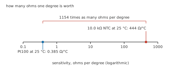
The gap is about three decades wide on this axis, and sensitivity is the one contest platinum loses.
What platinum offers instead is a characteristic somebody else has already written down, so a replacement element reads the same as the one it replaced. Why any of this works at all is the subject of temperature effects on resistance.
Practitioner
Taking a reading, and what the leads take from it
Over a moderate span a single coefficient describes the element well enough to work with:
For platinum that coefficient is quoted as 0.00385 /°C, and it is fixed by the standard rather than by the manufacturer. Put 100 °C into it and the element should read 138.50 Ω.
Measuring that resistance means passing a known current and reading the voltage it produces:
At an excitation of 1.00 mA the element develops 138.5 mV. The current is deliberately small, for reasons Layer 3 gets to.
A sensitivity of 0.385 Ω/°C means the whole useful signal is a few tens of ohms, and the sensor is rarely on the same bench as the instrument. Cable has resistance, the element and the cable are in series, and the instrument has no way to tell one from the other:
Worked example — Two wires to a sensor across the room
A Pt100 of 100.00 Ω sits at 100 °C, so its own resistance is 138.50 Ω. It is connected with two conductors, each of them 0.42 Ω.
Element and both leads are in series, so the instrument sees 139.34 Ω.
Inverting the coefficient on that figure gives 102.18 °C, an error of 2.18 °C on a sensor whose whole reason for existing is that it can be trusted to a fraction of a degree.
The cure is one more conductor.
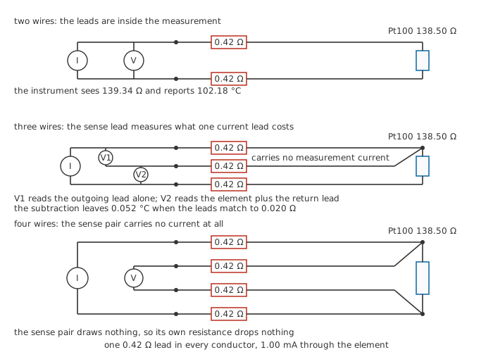
Three wirings, one element, one lead resistance. Trace the third conductor in the middle panel: it reaches the element but ends on voltmeter terminals.
With two wires the leads are part of the measurement, and there is nothing to be done about that except keep them short and cold.
With three wires a third conductor runs to the same terminal of the element as one of the current-carrying leads and ends at a high-impedance input. It carries no measurement current, so it drops no voltage, which makes it a probe sitting at the element's own terminal. The instrument now has two readings: one across the element plus the return lead, one across the outgoing lead alone. Subtract, and the leads cancel to the extent that they match each other. With cable matched to 0.020 Ω, 0.052 °C survives.
With four wires the current goes out and back on one pair while the voltage is sensed on a second pair that draws essentially nothing. Since the sense pair carries no current it drops no voltage, so lead resistance contributes 0.00 °C to the answer whatever the cable does. This is the same Kelvin idea a four-terminal current-sense resistor uses, moved from a shunt onto a sensor.
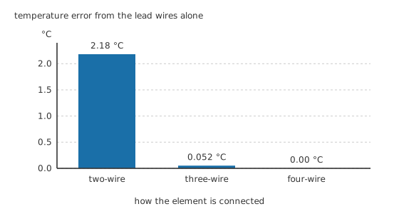
One scale, three wirings. The four-wire bar has no height because it has no error.
Engineer
The straight line is a summary of the curve
The coefficient Layer 2 used is not a slope the element actually has. It is defined from two fixed points: the resistance at the ice point and the resistance at the steam point, divided by the hundred degrees between them and by the ice-point resistance. That makes it an average across that interval rather than the slope at any particular point inside it.
The published characteristic above the ice point is quadratic, R(T) = R0(1 + A·T + B·T²), with A close to the quoted coefficient and B small and negative. Below the ice point the standard adds a further term. The negative B is why the element's slope shallows as it warms: at 100 °C the curve gives 138.51 Ω where the straight line gave 138.50 Ω — a difference nobody need care about. At 200 °C the same straight line says 177.00 Ω while the curve says 175.86 Ω, and now it matters.
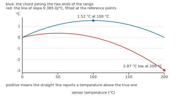
Plotted as deviation, because the characteristic itself looks straight and would show nothing.
Each straight line fails in its own way. Extend the coefficient's line out to 200 °C and it reports 2.97 °C low, because it was fitted at the bottom of the span and the real slope has been shrinking ever since. Fit the chord to both ends of the span instead and the ends come out right while the middle bulges: at most 1.52 °C, at 100 °C, halfway along.
Neither error is a defect in the element. Both are the price of a straight line, and an instrument that inverts the published polynomial rather than the coefficient pays neither. This is worth knowing before you write your own conversion, because a Pt100 handled linearly is accurate over a narrow window and quietly wrong outside it.
Why the excitation current is kept small
The instrument has to push current through the element to read it, and that current dissipates power in the thing whose temperature is the answer.
At 1.00 mA into 138.50 Ω the element dissipates 138.5 µW. How much that warms it depends on how well it is coupled to what it is measuring, which the manufacturer quotes as a dissipation constant in milliwatts per degree. Take an illustrative 20.0 mW/°C and the self-heating comes to 0.0069 °C, which disappears under everything else in the budget.
That comfortable result belongs to the RTD's low resistance. Run the same current into the thermistor from Layer 1 and the dissipation is a hundred times larger, which is why thermistor circuits work at far smaller currents. The thermistor lesson takes that argument further.
Raising the excitation to get a bigger signal spends this margin quickly, because the heating goes as the square of the current while the signal goes only as the current.
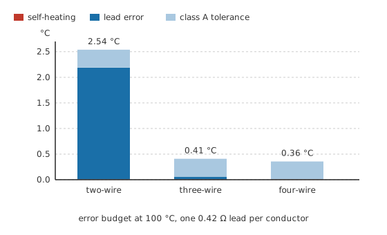
Same element, same current, same class. The blue segment is the only thing the wiring changes.
Stack the contributions and the shape of the problem is obvious. Two wires put the total at 2.54 °C and nothing else in the budget is worth improving until that is dealt with; three wires bring it to 0.41 °C and four to 0.36 °C, at which point the element's own tolerance is all that is left. Many industrial instruments read the element in a bridge rather than with a current source, which changes the arithmetic but not the argument; the Wheatstone bridge lesson works that version through.
Professional
Classes, interchange and the rest of the error
An element is sold against a tolerance class, and the class is an expression rather than a number. The tighter of the two common ones allows 0.15 °C plus 0.002 of the temperature in degrees; the looser allows 0.30 °C plus 0.005. At 100 °C those come to 0.35 °C and 0.80 °C; at 200 °C, 0.55 °C and 1.30 °C.
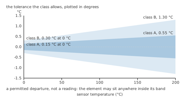
The band is what the element is permitted to be, before the instrument and the wiring have added anything.
The band narrows to its tightest at the reference point and opens either side of it, which mirrors how the elements are actually made: they are trimmed to value near the ice point, and any small error in the shape of the characteristic then grows with distance from where it was trimmed.
What a class really buys is interchange. Because the characteristic is standardised, an element from any manufacturer in a given class can replace any other and the instrument needs no recalibration. That is unusual among sensors and it is most of the reason process plant is full of them.
A Pt1000 is the same platinum and the same standardised characteristic, scaled to 1.00 kΩ at the same reference point. Its sensitivity is 3.85 Ω/°C against the Pt100's 0.385 Ω/°C, so the same pair of leads that cost 2.18 °C on a Pt100 costs 0.218 °C here. Two-wire wiring becomes defensible on short runs, and the same excitation current gives ten times the signal, at the cost of ten times the self-heating for that current.
Construction decides most of the rest. Wire-wound elements are the more accurate and reach higher temperatures, but the winding is delicate and dislikes vibration. Thin-film elements are cheap, small, fast and rugged, and the platinum film is bonded to a substrate that expands at a different rate, so mechanical strain shows up as an apparent temperature and repeated thermal cycling can leave a small permanent shift. Neither type enjoys being bent at its leads.
Speed is where the laboratory thermometer analogy pays out. The element sits inside a sheath, often inside a thermowell as well, and the reading follows the process through all of that thermal mass rather than in spite of it. A bare film element in moving liquid follows a change quickly; the same element inside a heavy well in still air lags it badly, and the gap between the two is wide. A sensor that responds slowly is not inaccurate, but a control loop closed around it behaves as though there is a delay in the plant, because there is.
Precision work turns up two smaller effects. Junctions between dissimilar metals in the lead path generate small thermal voltages that add to the measured drop, which good instruments cancel by reversing the excitation current and averaging the two readings. And at high temperature the insulation between the element and its sheath stops being infinite, putting a leakage path in parallel with the element and pulling the reading low.
The class tolerance is the element alone. Instrument accuracy, lead error, self-heating, the calibration of the excitation current and the thermal contact between the sheath and whatever you actually wanted the temperature of all sit on top of it. The last of those is usually the largest — and it is the one no datasheet can quote for you. Above the platinum range a thermocouple takes over, and it trades this whole discussion of ohms for one about millivolts and reference junctions.
Common mistakes
- Wiring a remote sensor with two conductors. The leads are inside the measurement and the error is silent, repeatable and looks exactly like a real temperature. Three wires cost one more core in the cable.
- Assuming three wires cancel whatever the cable does. The cancellation is only as good as the match between the two current-carrying conductors, so mixing gauges, splicing one leg or terminating them differently puts the error straight back.
- Treating the quoted coefficient as the element's slope. It is an average defined between two fixed points, and using it as a slope costs a degree or more once you are well away from them.
- Raising the excitation current to get a cleaner signal. The dissipation climbs as the square of it while the signal climbs only in proportion, and the sensor ends up reporting its own heating.
- Quoting the class tolerance as the accuracy of the measurement. It describes the element on its own, before the instrument, the leads and the thermal contact have had their say.
Frequently asked questions
What does Pt100 mean?
Platinum, with a nominal resistance of 100 Ω at the ice point. A Pt1000 is the same material and the same standardised characteristic scaled to ten times that resistance at the same reference point.
Should I use three wires or four?
Three is the industrial default and removes almost all of the lead error for the cost of one extra conductor. Four removes the rest of it and is what laboratory, calibration and reference work uses. Two is for a sensor that is close enough to reach.
Why does my RTD read high?
Series resistance in the path, most often lead resistance on a two-wire connection, but also a corroded terminal, a poor crimp or a splice added when the cable was extended. All of it adds to the element and all of it reads as extra temperature.
RTD or thermistor?
A thermistor is far more sensitive, cheaper and faster, over a narrow range and with a characteristic that varies between parts. An RTD is less sensitive and more expensive, over a wide range, with a characteristic set by a standard so that parts interchange. Repeatability and range point to platinum; sensitivity and cost point to the thermistor.
Can I extend the cable to an RTD?
On four wires, freely, as long as the sense pair stays a sense pair. On three wires, only if the extension keeps the two current conductors matched to each other. On two wires, every metre of extension is a temperature error you will not see.
Knowledge check
A Pt100 of 100.00 Ω sits at 100 °C and is wired with two conductors of 0.42 Ω each. What does the instrument report? (Show answer)
Why does the third conductor of a three-wire connection not add to the reading? (Show answer)
Across 0 °C to 200 °C, how far does a straight line depart from the real platinum characteristic? (Show answer)
An element at 100 °C is excited with 1.00 mA. How much does the measurement warm it? (Show answer)
What does a class A element promise at 200 °C, and how does that compare with class B? (Show answer)
References
- International Electrotechnical Commission, IEC 60751, Industrial platinum resistance thermometers and platinum temperature sensors — the standardised platinum characteristic and its coefficients, the nominal temperature coefficient used throughout this lesson, and the class tolerance expressions plotted in Layer 4.