
Quick Answer
A resettable fuse is a polymer whose resistance jumps by a factor of hundreds when it gets hot. An overload heats it, the rising resistance limits the current, and its own remaining current keeps it hot. Removing the supply lets it cool and recover.
Intuition
A fuse that changes its mind
An ordinary fuse solves the overload problem by ending itself. That works, and it has one obvious cost: somebody has to come and fit a new one. For a mains input on a piece of equipment that is fine. For a USB port that gets short-circuited whenever a cable is inserted crookedly, or for a satellite, or for anything sealed shut at the factory, it is not.
The resettable fuse solves the same problem without the ending. It is a lump of polymer filled with conductive particles — enough of them, packed closely enough, that they touch each other in chains from one electrode to the other. Cold, that makes it a reasonably good conductor.
Warm it up and the polymer expands. Not much, but the particles are only just touching, and a small expansion pulls the chains apart. The resistance climbs, sharply.
What makes it a protection device rather than a curiosity is that the heat comes from the current itself. A fault drives current through the polymer, the polymer warms, the resistance rises, and the rising resistance both restricts the fault and keeps the device hot — because a smaller current through a much larger resistance is still plenty of watts. So it latches. It stays in the high-resistance state until you take the supply away.
Then it cools, the polymer contracts, the chains re-form, and it works again. Which is the whole selling point, and also, as the fourth layer explains, the source of everything wrong with it.
Safety
A polymer PTC is not a fuse and it is not a substitute for one in every position. Two differences matter and neither is a matter of degree. It does not isolate: tripped, this illustrative device still passes 208 mA and dissipates 2.50 W, so the fault is still connected to the supply and the device is sitting at 125 °C for as long as it remains so. Anything that has to be disconnected — because it is on fire, because it is a mains circuit, because a person is going to touch it — needs a fuse or a breaker. And it has no breaking capacity, so where the available fault current is large it is the wrong device entirely. Every number in this lesson is an explicitly invented illustration and none of them is a rating. Hold current, trip current, maximum voltage and maximum fault current belong to a specific part and to the standards it was approved against. A tripped device is hot enough to burn and hot enough to damage what is next to it on the board, and it will stay that way indefinitely, which is not something a fuse ever does.
Practitioner
Three and a half decades in fifteen degrees
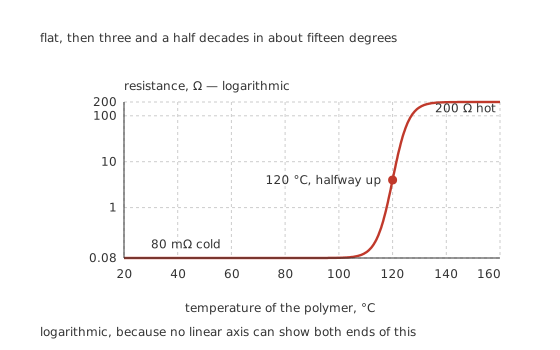
Logarithmic, because no linear axis can show both ends of this.
The device's whole character is that curve. Below its switching temperature it is a resistor of 80 mΩ; above, it is a resistor of 200 Ω; and the transition takes about fifteen degrees.
Worked example — What it costs when nothing is wrong
Carrying 3.0 A through 80 mΩ the device drops 240 mV and makes 720 mW of heat.
Against an illustrative 40 °C per watt to its surroundings, that settles it at 53.8 °C — comfortably below the 120 °C switching point.
That drop is the price of admission, and it is larger than a fuse of comparable rating would charge. A PTC in a supply path is a series resistance you have chosen to accept.
The resistance is not stable even below the knee. A PTC's cold resistance is specified as a range rather than a value, it changes with temperature well before the switching point, and it changes again with the device's history. Anything that needs a predictable series resistance — a current-sense path, a precision reference feed — should not have one of these in it.
The switching temperature is a material property. It is set by the polymer's melting range, which is why parts are offered in a small number of switching temperatures rather than a continuum, and why the device's behaviour depends so completely on how well it can get rid of heat.
The thermal path is part of the component. Everything below turns on that 40 °C per watt, and it is not a property of the part alone: it is the part plus its pads, plus the copper they sit on, plus the airflow. Two identical devices on two different boards have two different thresholds, and a device soldered to a large ground pour can carry noticeably more than one on thin tracks. That makes a PTC one of the few components whose specification you can meaningfully change by changing the layout, and it also means the datasheet's numbers are quoted for a stated test board.
Ceramic PTCs are a different family. They are barium titanate rather than polymer, switch at higher temperatures, tolerate higher voltages, and have a much larger cold resistance — so they belong in mains-adjacent jobs like motor-start circuits and degaussing, not in a low-voltage supply path where the drop would be unacceptable. The two share a name and a graph shape and almost nothing else.
And the package tells you very little. The common radial-leaded and surface-mount bodies span a wide range of hold currents in the same outline, and unlike a fuse the part is rarely marked with anything readable. A PTC on an unfamiliar board is best identified from the circuit it is in.
Engineer
The latching is an intersection that stops existing
Nothing in the device decides to trip. What happens is that a solution to an equation disappears.
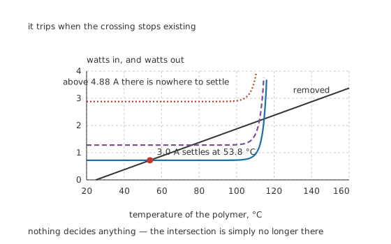
Nothing decides anything — the intersection is simply no longer there.
Worked example — Where the threshold is
Heat arriving is the current squared times the resistance the device happens to have. Heat leaving is its temperature rise divided by 40 °C per watt.
At 3.0 A the generation curve is flat while the polymer is cold, crosses below the removal line at 53.8 °C, and the device sits there indefinitely.
Raise the current and that crossing slides up the curve towards the knee. At 4.88 A it disappears: above it, generation exceeds removal at every temperature below the switching window, so there is nowhere to settle. That is the entire mechanism, and the margin over the working current here is only 1.63 times.
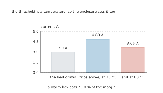
A warm box eats 25.0 % of the margin.
Worked example — What the enclosure does to it
The threshold is a temperature dressed as a current, so anything that changes the temperature changes the threshold.
Move the same device from 25 °C to a 60 °C enclosure and the available rise before switching is smaller. The threshold falls from 4.88 A to 3.66 A, a derating of 25.0 %.
Against a 3.0 A load that leaves a margin of only 1.22 times, against 1.63 on the bench. This is why PTC datasheets carry a derating table rather than a single number, and why a design proved on a cold bench trips in service.
A datasheet splits that one threshold into two. It quotes a hold current, which the device is guaranteed not to trip below, and a trip current, which it is guaranteed to trip above, and there is a wide gap between them. The model here gives one number because it has no tolerances and no time in it; a real part has both, and the gap is where they live. Design against the hold current, and check what the trip current does to whatever is downstream.
Professional
What it costs to get the resetting
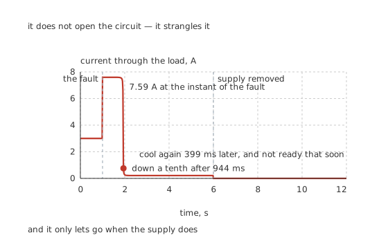
It does not open the circuit — it strangles it.
Worked example — Following one fault through
A fault through 1.5 Ω on a 12 V supply drives 7.59 A through the device at the instant it appears.
The polymer's 50 mJ per degree against 40 °C per watt gives a thermal time constant of 2.0 s, so the current is down a tenth after 944 ms and settles at 208 mA.
That residual current, through 57.6 Ω, is 2.50 W — enough to hold the device at 125 °C for as long as the supply is connected. The tripped resistance is 720 times the cold one, and it is a resistance rather than an open circuit.
Compare that with the fuse worked through in the previous lesson, which clears a hundred-amp fault in well under a millisecond. This device takes most of a second — 944 ms against well under a millisecond — to bring one fault down a tenth. For a fault that only needs limiting, that is fine. For a semiconductor, it is a thousand times too slow.
Recovery is not the same as being ready. This model's resistance is back near 80 mΩ 399 ms after the supply goes, because that is how fast the device cools. Real polymer devices stay elevated for far longer, sometimes minutes, because the conductive chains have to re-form as the polymer re-crystallises — a mechanism that is nowhere in the arithmetic above, and one reason a device that has just tripped often behaves oddly for a while.
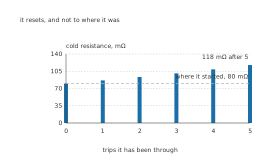
It resets, and not to where it was.
Worked example — It comes back different every time
At a declared 8.0 % increase per trip, the device's cold resistance climbs from 80 mΩ to 118 mΩ after 5 trips.
That is 1.47 times where it started, and it does not come back down.
So the voltage drop in normal service grows, the temperature in normal service grows with it, and the trip threshold falls. A device that has tripped many times will eventually trip at its working current.
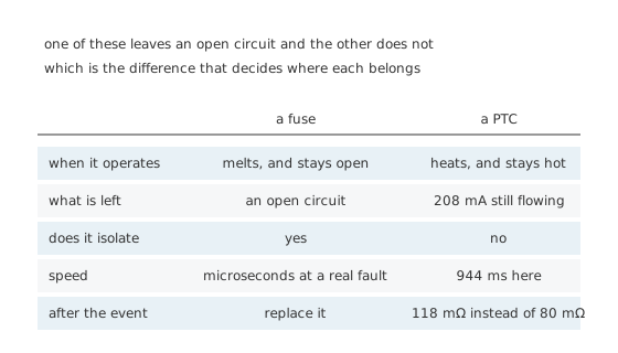
One of these leaves an open circuit and the other does not.
Where each belongs
A PTC is right where the fault is expected and harmless. USB ports, battery packs, motor supplies on a toy, a bench supply's output, transformer secondaries, anything a user can short by accident and will short again next week. Sealed or inaccessible equipment is the other clear case.
A fuse is right where the fault must be disconnected. Mains inputs, anywhere the available fault current is large, anywhere a fire is the failure being designed against, and anywhere something downstream needs clearing in microseconds rather than in a second.
Fitting both is common and sensible. A PTC handles the everyday overloads without a service call, and a fuse behind it handles the fault the PTC cannot: the two are protecting against different things at different speeds.
Watch the drop, not just the trip. 240 mV in a supply path is not nothing, and it grows as the device ages. In a low-voltage rail with a tight tolerance it can be the reason a design fails to meet its specification.
A PTC in series with a battery is a special case worth knowing. Many lithium cells have one built into the cap, and it is protecting against a short across the terminals rather than against anything the equipment does. It is also one of several protections, not the protection, which battery types picks up.
Common mistakes
- Treating it as a fuse — tripped, this device still passes 208 mA and dissipates 2.50 W. It limits the fault; it does not disconnect it.
- Designing to the threshold on the bench — 4.88 A at 25 °C becomes 3.66 A in a 60 °C enclosure, a derating of 25.0 %, and against a 3.0 A load the margin falls from 1.63 times to 1.22.
- Ignoring the series resistance — 80 mΩ at 3.0 A is 240 mV and 720 mW, in a supply path, permanently.
- Expecting it to protect a semiconductor — it takes 944 ms to bring this fault down a tenth, where a fuse clears a real short in microseconds.
- Assuming it resets to where it was — at a declared 8.0 % growth per trip the cold resistance is 118 mΩ after five, 1.47 times the original, and it never comes back down.
- Confusing thermal recovery with readiness — the model's resistance is back near 80 mΩ 399 ms after the supply goes, and a real device takes far longer while the polymer re-crystallises.
Frequently asked questions
How does a resettable fuse know when to trip?
It does not know anything. Heat arriving is the current squared times its resistance, heat leaving is its temperature rise over its thermal resistance, and normally the two cross somewhere cool — 53.8 °C at 3.0 A here. Above 4.88 A that crossing stops existing, so there is nowhere to settle and the device runs away to its high-resistance state.
Why does it stay tripped?
Because the residual current keeps it hot. At 12 V the tripped device sits at 57.6 Ω, passing 208 mA and dissipating 2.50 W, which holds it at 125 °C. Take the supply away and the heat source goes with it.
Can I use one instead of a fuse?
Only where the fault has to be limited rather than disconnected. A tripped PTC still connects the fault to the supply and still has 208 mA flowing, it has no breaking capacity, and it takes 944 ms here where a fuse takes microseconds. On a mains input, or anywhere a fire is the failure mode, fit a fuse.
Does it really go back to normal?
Nearly. At a declared 8.0 % growth per trip the cold resistance goes from 80 mΩ to 118 mΩ after five trips, 1.47 times where it started, and it stays there. The drop and the self-heating grow with it, so the trip threshold falls a little each time.
Why does my PTC trip when the equipment is warm?
Because the threshold is a temperature in disguise. In a 60 °C enclosure this device has less rise available before it switches, so it trips at 3.66 A instead of 4.88 A — 25.0 % less. Datasheets carry a derating table for exactly this.