

Quick Answer
Current limiting is the deliberate restriction of current in a circuit to a value the components can survive. Some loads draw destructive current if connected directly to a supply, and every supply can deliver a damaging current into a fault. A series resistor is the simplest limiter; active circuits are the precise ones.
Intuition
The limiter on the van
Delivery vans are often fitted with a speed limiter. The engine is capable of far more, and the driver may want more, but a device in between decides that the vehicle will not exceed a set speed. Nobody thinks of this as a fault; it is a deliberate limit placed where an unlimited capability would be dangerous.
Circuits need the same thing, for a reason that follows directly from Ohm's law. A voltage source offers a voltage and leaves the current to the load, and some loads make a very poor job of it. An LED connected straight across a battery draws whatever the supply can provide, gets hot, and destroys itself in a fraction of a second. It has no useful resistance of its own to do the deciding.
That leaves the job to something else, and the simplest candidate is a resistor in series with the load. The resistor has a definite resistance where the LED has none worth the name, so putting the two in one loop lets the resistor set the current for both. It is inelegant and it wastes a little energy, and it appears in more circuits than almost any other technique.
Awkward loads are only half of the reason. The second situation reaches every circuit: when something fails — a short across a rail, a motor that jams, a probe that slips — the current is held back by nothing but the source and the wiring, and that can be enormous. A deliberate limit turns an event that would melt copper and start a fire into one that trips, blows a fuse or simply refuses to deliver more.
Both cases rest on one fact. Some part of the loop always settles how much current flows, and where the designer has not chosen which part, the source and the wiring settle it between them, at whatever value the physics allows.
Practitioner
Sizing the simplest limiter
A load with a nearly fixed voltage across it — an LED, a Zener diode, a base-emitter junction — leaves the rest of the supply voltage to appear across a series resistor, and that resistor sets the current:
Worked example — An indicator LED on a 5 V rail
An LED with a forward voltage of 2 V is to run at 15 mA from a 5 V supply.
Subtracting the forward voltage from the supply leaves what the resistor must drop, and dividing by the wanted current gives its value: 200 Ω. At that current it dissipates 45 mW, so a small surface-mount part is comfortable.
The E12 series does not include that figure, so the nearest E12 part is 220 Ω, giving an actual current of 13.6 mA. Which series you are working from matters here: E24 does carry 200 Ω, so on a design drawing from E24 no substitution is needed at all. For an indicator either outcome is entirely acceptable. Where a substitution does have to be made, take the next value up rather than down, since that errs towards less current rather than more.
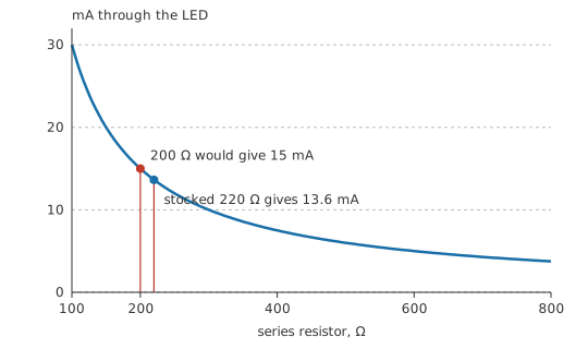
What makes the technique work is that the current ends up set by the one resistance in the loop that is actually known. Any load whose own voltage is roughly constant, and whose own resistance is not, can be driven this way.
The dissipation needs checking every time. On a higher rail the value that gives the right current can easily exceed a small part's rating, and a resistor run beyond its rating drifts before it fails — see resistor power rating.
Scaling up is where the method runs out. Everything the resistor drops becomes heat, so limiting a one-ampere load from a rail well above its working voltage wastes watts continuously, and once that waste heat becomes inconvenient a current source or a switching driver takes the resistor's place.
Faults are a different job again, handled by different devices. A resistor sets a working current, while a fuse permits the working current and opens on a fault. Fuses, circuit breakers, resettable polymer devices and electronic limiters are protection rather than operating limits, and a design usually needs both.
Inrush asks for something different from either, because there the limit has to be temporary. Capacitive inputs and cold filaments draw far more at switch-on than in steady state, and a thermistor with a negative coefficient, a soft-start circuit or a pre-charge resistor bypassed by a relay each handle that in their own way — see loads and loading.
Engineer
What the resistor buys, and what it costs
A series resistor works by moving the current onto quantities that are known, and away from the load's own characteristic — which drifts with temperature and varies with manufacturing spread from one batch to the next.
Worked example — Tolerating a load that varies
Suppose the same LED's forward voltage is anywhere between 1.8 V and 2.2 V across a production batch, with the 220 Ω resistor fitted.
At the low end the current is 14.5 mA; at the high end it is 12.7 mA. The spread is 12.1 % of the design current — noticeable, and entirely survivable.
Without the resistor there is nothing to absorb that variation, and the same spread in forward voltage produces a current change of orders of magnitude, because the load's current depends exponentially on the voltage across it. The resistor converts an exponential sensitivity into a linear one. That conversion, more than the limiting itself, is why one is fitted in every case.
Headroom buys that tolerance and charges waste for it. The larger the fraction of the supply that appears across the resistor, the less the load's variation matters, and the more energy goes into heating the resistor.
Worked example — The same LED on a 12 V rail
Running the same part at the same current from 12 V needs 667 Ω, dissipating 150 mW.
Only 16.7 % of the energy drawn reaches the LED; the rest heats the resistor. For one indicator the loss is irrelevant. Across a hundred of them, or in a lighting product, that ratio is what sends a designer to a switching driver instead.
A resistor sets the current only while the supply voltage is what you assumed it would be. On a rail that rises, a resistor-limited load takes proportionally more current; on one that sags it takes less. So resistor limiting is inadequate wherever the supply itself is uncertain, such as directly from a battery over its discharge range.
Active limiting cuts that dependence away. A transistor with a sense resistor in its emitter or source, or an op-amp driving a pass element from a current measurement, holds the current at a set value across a wide range of supply and load. This is a current source doing protection work, and it is what sits behind a bench supply's current-limit control.
Response time is where limiting and protection part company. A resistor limits instantly and permanently, an electronic limiter responds in microseconds, and a fuse takes anywhere from milliseconds to many seconds depending on the overload, which is why it is characterised by a current-time curve rather than by a single number. Since semiconductors fail faster than most fuses open, fuses end up protecting wiring while electronics protect semiconductors, and matching the response to what needs protecting is the design decision.
A foldback limiter behaves differently again under a hard fault. Rather than holding its set current into a short it reduces it, cutting dissipation in the pass device. The cost is that it can fail to start a load whose inrush looks like a fault, latching at a low current instead of coming up.
Professional
Choosing a limiter
Which device to fit depends on the failure being prevented. A series resistor sets an operating current, while a fuse protects wiring against sustained overload. A resettable polymer device responds slowly and suits repeated, self-clearing overloads; an electronic fuse gives fast, precise, resettable protection with monitoring. A varistor sits outside all of those, since it clamps a voltage surge rather than limiting current at all. Using one where another belongs is a common and expensive error.
Protective devices also have to be coordinated with each other. In a chain of them the one nearest the fault should operate first, so that a fault in one branch does not take out the whole system. That requires the upstream device to be slower or higher-rated than the downstream one across the whole current range, which is a comparison of curves rather than of ratings.
A pass element dissipates most during a fault rather than in ordinary use. A linear limiter holding its set current into a short has nearly the full supply voltage across it, so its dissipation peaks exactly when the situation is already abnormal. Thermal shutdown, foldback and hiccup modes that retry periodically all exist to keep that condition survivable.
Current limiting is a source specification as well as a circuit technique. A bench supply's current limit saves more parts than any other practice at a workbench: set it just above the expected draw, and a wiring mistake produces a supply sitting in current limit rather than a destroyed board. Set it before the circuit is powered for the first time, not after something has already gone wrong.
Parallel branches each need a limit of their own. Devices sharing a load want individual ballasting whenever their characteristics carry a negative temperature coefficient, since the hottest one otherwise takes an increasing share — the temperature effect that makes parallel LEDs behind a single resistor a poor design, and parallel LEDs each with their own resistor an acceptable one.
Safety
Current limiting is a fire-prevention measure as much as a component-protection one. An unlimited fault current in wiring not designed for it heats the conductor faster than the insulation can shed the heat, and the result is a cable fire inside a wall, a loom or an enclosure.
Do not fit a larger fuse to stop one blowing, and never replace a fuse with wire, foil or a bolt — the fuse is sized to protect the cable behind it, and defeating it moves the failure to a place you cannot see. Do not rely on a supply's current limit as a safety device on mains-connected equipment; it protects the supply, not you. Do not test a protective device by creating a deliberate fault, and treat battery and capacitor circuits as capable of very large fault currents regardless of their low voltage — see batteries in series and parallel and open and short circuits.
Where equipment is connected to the mains, protective device selection is a regulated matter and follows the installation standard, not a calculation done at a bench. General practice is in electrical safety fundamentals.
Every rating is stated at a temperature, and it derates above that temperature. A fuse rated at a given current in free air at 20 °C carries meaningfully less inside a hot enclosure, and a polymer device's trip current falls as the ambient rises. Protection sized at room temperature can nuisance-trip in service or, worse, fail to trip when it matters.
Common mistakes
- Connecting an LED directly across a supply — it has no useful resistance of its own, so the current is set by the supply and the LED destroys itself.
- Sizing the resistor and forgetting its dissipation — the correct value on a higher rail can exceed a small part's rating, and an overloaded resistor drifts before it fails.
- Relying on a series resistor when the supply varies — the current tracks the supply voltage. A battery across its discharge range needs active limiting.
- Putting several LEDs in parallel behind one resistor — the one with the lowest forward voltage takes most of the current, and gets worse as it heats.
- Fitting a larger fuse when one keeps blowing — the fuse protects the wiring. Increasing it moves the failure into the cable.
- Confusing surge clamping with current limiting — a varistor limits voltage, a fuse limits duration, a resistor limits current. They are not interchangeable.
Frequently asked questions
Why do LEDs need a current-limiting resistor?
Because an LED's current rises steeply with the voltage across it and it has no useful resistance of its own. Without something to set the current, it draws whatever the supply can deliver and destroys itself.
How do I calculate the resistor for an LED?
Subtract the LED's forward voltage from the supply voltage, then divide by the current you want. Choose the nearest preferred value upward, and check the resistor's dissipation against its rating.
Is a series resistor good enough for high-power loads?
Rarely. Everything it drops becomes heat, so at high current the waste is substantial. A constant-current driver or a switching regulator does the same job without dissipating the difference.
What is the difference between current limiting and a fuse?
A limiter restricts the current continuously to a set value. A fuse permits normal current and opens permanently on an overload. One is an operating limit, the other is protection, and most designs need both.
Why does my bench supply have a current limit control?
So that a wiring error results in the supply going into current limit rather than destroying the circuit. Setting it just above the expected draw before powering a new board is the single most effective bench habit.