
Quick Answer
A varistor is a resistor whose resistance collapses once the voltage across it passes a designed level. Below that level it does almost nothing. Above it, it conducts hard, holding the voltage down while the surge's energy turns into heat inside it. Each event uses up a little of the part.
Intuition
A resistor that stops being one
A varistor spends nearly all of its life doing nothing. Sitting across a supply at its ordinary working voltage it behaves like many megohms, drawing a current you would need a careful meter to find. Then a transient arrives, the voltage across it climbs past the level it was built around, and its resistance falls by orders of magnitude in nanoseconds. It conducts hard, the voltage stops climbing, and whatever the surge was carrying goes into the varistor as heat.
The name says the job. A varistor is a variable resistor, and what varies it is the voltage on its own terminals rather than a knob. The resistor you already know holds one value whatever you do to it, and that constancy is what makes it useful. Here the value moving is the entire point.
Think of a crumple zone. It is not there to bounce an impact back; it is there to be destroyed slowly enough that the people behind it are not. The energy has to go somewhere and the crumple zone volunteers. A varistor volunteers the same way, and like a crumple zone it is not the same part afterwards.
Below its threshold it is invisible; above it, it is a deliberate short circuit, and open and short circuits covers why a controlled short is sometimes what a designer wants.
An illustrative transient of 1.00 kV open circuit, meeting a clamp that holds 430 V, reaches the protected circuit smaller by a factor of 2.33. Every number on this page is arithmetic on stated illustrative values, never a measurement and never a rating for a real part.
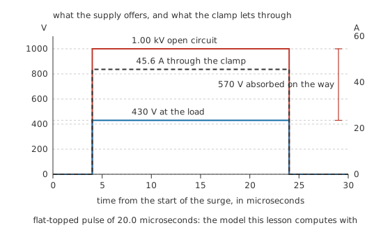
The clamp does not send the surge back where it came from. It holds the node down and takes the difference as heat.
Practitioner
Where it goes and what it holds
A varistor goes across the thing it protects rather than in line with it. Its two terminals connect to the two conductors whose voltage difference matters, and the load hangs off the same pair. That parallel position is what lets the part do nothing during normal service and everything during a transient: it sees only the voltage, never the load current.
Something resistive in the line ahead of it helps a great deal. A small deliberate resistance, or the impedance of a metre or two of cable, gives the transient somewhere else to lose energy on the way in.
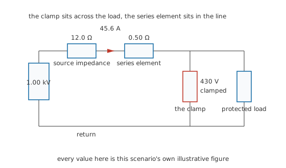
Trace it: clamp and load share one node and one return, so they sit in parallel. The series element is in the line, not across it.
Three separate voltages get muddled together here, and telling them apart is most of choosing a part sensibly.
The working level is what the varistor sits across day after day without conducting. In the scenario this lesson computes with, that is 275 V. The clamping level is what it holds while it conducts hard, here 430 V, and it is not a threshold that gets crossed and then held perfectly: a varistor's characteristic is a curve, so the voltage across it keeps creeping up as the current through it climbs steeply, and any clamping figure is that curve read at one stated current. The let-through is what reaches the protected circuit, and with the clamp in parallel with the load those are the same node. The let-through therefore is the clamping level.
That last point decides whether a clamp is worth fitting. Nothing behind a varistor is protected below the voltage the varistor clamps at, so if the equipment cannot survive 430 V, this is the wrong clamp and no energy rating changes that.
The source deserves a word too. A transient source is not a battery holding a fixed voltage; it has an open-circuit figure with an impedance behind it, and the instant the clamp starts conducting, that impedance drags the source's own terminals down.
In the scenario, 1.00 kV behind 12.0 Ω falls to 452.8 V at the source terminals once 45.6 A is flowing, and the 0.50 Ω element in the line takes a further 22.8 V. What is left at the load is the clamping level. The clamp sets the node voltage, and everything upstream arranges itself around that.
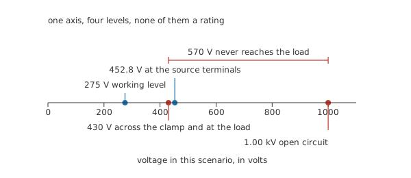
None of these four is a rating. They are this one scenario's own arithmetic.
Safety
The component in this lesson lives permanently across a supply, which is the one position where a component failure is also a fire. Treat it that way.
A varistor fitted across mains conductors is mains-connected wiring, with everything that implies about competence, isolation and proving dead before touching. Electrical safety fundamentals sets out the practice and it is not repeated here. A degraded part draws a standing current at the working voltage and warms itself continuously, which is why commercial protectors put a thermal disconnect in series with the clamp and why the clamp is fused. Both of those are designed-in features, specified against the fault energy they may have to interrupt, and neither is something to improvise on a bench.
Replace a varistor only with the part the equipment manufacturer specifies. A clamp with the wrong working voltage either conducts in normal service or never conducts at all, and both failures look identical from the outside.
Nothing here is an instruction to test a varistor. Do not raise a voltage across one until it conducts, do not apply a surge to one to see what it does, and do not run one to destruction to find its limit. The illustrative arithmetic below reaches tens of kilowatts on paper, which is the entire reason the experiment is worthless.
Engineer
Joules, not volts
The voltage question is the easy one, and it is the one every datasheet answers first. The question that decides whether a clamp survives is how much energy it has to swallow, and that depends far more on what is behind the transient than on the transient's own headline figure.
Start from the current. The clamp holds its own voltage, so the difference between the open-circuit figure and the clamping level appears across everything else in the loop, and that difference divided by the series resistance is the current the clamp must pass.
Worked example — What the clamp is asked to swallow
A transient of 1.00 kV open circuit reaches the board through 12.0 Ω of source impedance and a 0.50 Ω element in the line. The clamp holds 430 V across itself while it conducts.
The clamp takes 430 V off the open-circuit figure, leaving 570 V across a series path of 12.5 Ω, so the current through the clamp is 45.6 A.
That current pulls the source's own terminals down to 452.8 V, and the series element drops a further 22.8 V, which lands the protected node exactly at the clamping level.
The clamp is therefore holding 430 V while passing 45.6 A, which is 19.61 kW. Over 20.0 µs that comes to 0.392 J, against 0.912 J delivered by the source in the same interval.
That power figure deserves a second look — sustained, it would be an absurd thing to ask of a component the size of a coin. The interval is what makes it survivable: 19.61 kW for 20.0 µs is 0.392 J. Energy and power are different questions, and a clamp is specified against the first. Resistor power ratings and derating works through the same distinction for ordinary parts.
Then there is the rest of it. The source delivered 0.912 J, and the clamp absorbed 0.392 J, which is 43.0 % of it. The other 54.7 % stayed in the source's own impedance as 0.499 J, dissipated at 24.95 kW in something the designer neither chose nor controls, and the series element quietly took 20.8 mJ on the way past.
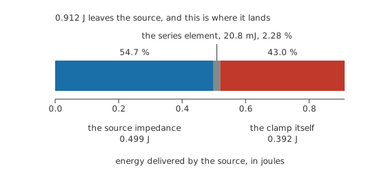
The clamp's share is the small part of the problem. Whatever sits upstream took most of it before the clamp ever conducted.
That is why the source impedance, and not the transient's headline voltage, is the number to worry about. Run the same 1.00 kV transient into the same clamp through a stiffer source of 6.0 Ω and the current climbs to 87.69 A, so the clamp swallows 0.754 J. Through a softer 25.0 Ω the current is only 22.35 A and the clamp gets away with 0.192 J. Same transient, same clamp, and what separates the two outcomes is the supply rather than the surge.
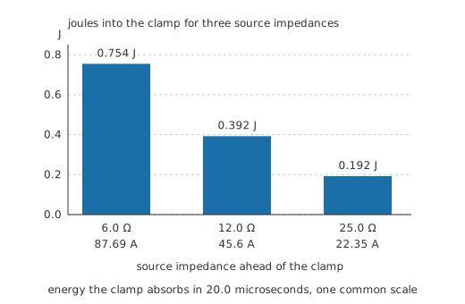
A stiffer supply is a harder job for the same clamp. This is the argument for putting impedance in the line.
There is one more way to look at the conducting clamp that makes its strangeness obvious. At the operating point above, it holds 430 V while carrying 45.6 A, so dividing one by the other gives an effective resistance of 9.43 Ω. Add that to the source impedance and the series element:
The loop totals 21.93 Ω, and Ohm's law across it returns 1.00 kV, which is the open-circuit figure back again.
The arithmetic closes, and it is still misleading. That 9.43 Ω is true at exactly one current and nowhere else. Halve the current and the resistance roughly doubles; take the part down to its working level and it is back to megohms. A varistor has a resistance only in the sense that any point on a curve has a slope — the same caution that applies to thermistors and to every other part whose value is set by something outside the circuit.
Professional
It wears out, and quietly
Everything so far would be equally true of an ideal clamp. The difference is why surge protection is a maintenance item rather than a fitting. Each conduction event heats a small volume of the material very quickly and unevenly, and the part does not come back exactly as it left. Its resistance at the working voltage drops a little. Nothing outside the part changes at all.
Follow that a few dozen events and the standing leakage climbs from something a meter struggles to find to something that matters. Take an illustrative starting leakage of 10.0 µA at the working level, and a model in which the leakage doubles for every 5.0 J of cumulative absorbed energy. That model is chosen so the trend has a shape worth drawing, not because it describes any particular part. After 20.0 J the leakage is 160 µA, which is 16 times where it started. At the scenario's 0.392 J per event that is about 51 surges.
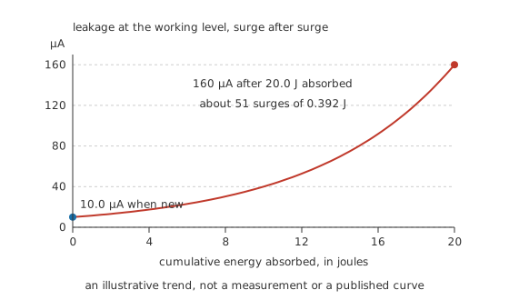
An illustrative trend drawn to show the shape, not a measurement and not a curve any manufacturer publishes.
The leakage matters because it dissipates. The part starts out burning 2.75 mW at the working level, which is nothing, and ends the same illustrative sequence at 44.0 mW, which is enough to warm a small component noticeably. Warmer material leaks more, more leakage warms it further, and a part far enough down that path can run away without any surge at all. This is the failure mode that sets fire to things, and it is why the temperature behaviour of the material is not a footnote here.
That is why a varistor is fused and thermally disconnected in any product built properly: the runaway then ends in an open circuit rather than a flame. It also explains what the indicator lamp on a surge-protected outlet strip is worth. Such a lamp generally reports that the path through the clamp is still intact, which a badly degraded part usually is, so a protector that has been quietly absorbing for years and a new one look identical from the front panel.
A varistor is also poor at several jobs it gets asked to do. It is not a filter: it does nothing to the frequency content of anything below its threshold, so the interference problem stays exactly where it was and belongs to electromagnetic compatibility instead. It is not a regulator, and a sustained overvoltage rather than a microsecond transient will put it into continuous conduction until something gives. It does not limit current, which is a different device's job with a different failure mode. And it cannot help at all with a transient that arrives common-mode on both conductors at once, because it only ever sees the difference between the two.
Where the energy is large or the equipment expensive, protection is built in stages: a high-energy clamp near the supply entrance, impedance in the line, and a faster, lower-clamping device at the equipment itself. Coordinating those stages is a design exercise of its own, and the sizing of every stage rests on the same energy arithmetic Layer 3 works through rather than on anything new. What a varistor contributes to that chain is bulk energy absorption at a coarse voltage, cheaply, once, and then again a diminishing number of times. Resistor failure modes puts that behaviour alongside the ways ordinary parts give up.
Common mistakes
- Choosing by working voltage alone — the working voltage only decides whether the part survives normal service. The clamping level decides whether the circuit behind it survives the surge, and the energy figure decides how many surges it gets.
- Treating a clamp as reusable protection — every event consumes a little of the part, and nothing visible from the outside reports how much is left. Surge protection has a service life.
- Fitting one with nothing in the line ahead of it — against a stiff source the clamp absorbs the whole transient by itself, and the same part in the same circuit lasts far longer with a little impedance upstream.
- Expecting it to survive a sustained overvoltage — a device built for microseconds conducting for seconds will overheat. That case belongs to a fuse and a disconnect, not to the clamp.
- Reading an indicator lamp as proof of protection — most indicators report that the path is intact, which a heavily degraded part usually is.
Frequently asked questions
What does a varistor actually do during a surge?
It becomes a low resistance across the supply, so the surge current flows through it rather than through the equipment, and the voltage at that node stops rising. The transient's energy ends up as heat inside the varistor.
Why does the clamping voltage matter more than the joule rating?
Because the clamping voltage is what the protected equipment actually sees. A part with a huge energy rating and a clamping level above what the circuit can survive protects the varistor, not the circuit. Check the clamping level first, then check whether the energy figure covers the events you expect.
How do I tell whether a varistor is still good?
Not easily, and not from the outside. Increased leakage at the working voltage is the symptom, and measuring it properly means an out-of-circuit test at a specified voltage that most benches are not set up for. In service the honest answer is to replace protection on a schedule rather than on inspection.
Can a varistor fail short circuit?
Yes, and that is its usual end. Enough absorbed energy leaves a permanent conducting path through the material, which is why the clamp is fused and why products put a thermal disconnect in series with it. A short across the supply that nothing interrupts is a fire.
Does a varistor protect against lightning?
It handles the induced transients that lightning couples into wiring some distance away, which is the common case. A direct strike carries energy in a different class entirely, and the protection for that is an installation design question rather than a component choice.