
Quick Answer
A resistor's failure modes are the handful of ways it stops being the value printed on it. Sustained overload chars the element and drifts the value upward. A single large pulse can open it in milliseconds. Moisture and sulphur attack the terminations. Open circuit is the usual end state; a short is rare.
Intuition
A rope frays, a filament snaps
A rope under too much load frays first. Strands go one at a time, the rope gets looser and weaker, and anyone watching can see it coming. A lamp filament does the other thing. It carries its current all evening and then goes dark between one second and the next, with nothing to see beforehand.
Resistors do both, and which one you get depends on how the abuse arrives. Slow overload is the rope. The element runs hot for hours or weeks, its material changes, and the value climbs while the part carries on working. A single large pulse is the filament. Enough energy arrives in a few milliseconds to break the element mechanically, and the part is open before anything had a chance to drift.
The fraying comes first often enough to be worth measuring. Take a 120 Ω resistor that spends its life at a mild overload. A modest event leaves it 2.4 % high, at 122.9 Ω. A worse one leaves it 12.0 % high, at 134.4 Ω. A severe one, the sort that discolours the body, can leave it 48.0 % high at 177.6 Ω and still conducting. Those three percentages are illustrative, chosen to show the shape of the movement rather than lifted from any part's data sheet. All three parts measure as resistors. None of them is the resistor the schematic asked for.

Equal percentage shifts are equal distances on that axis, which is the honest way to compare drift.
Practitioner
The arithmetic of an overload
A resistor's failure stops being mysterious once the sum is done, and the sum is short. Our 120 Ω part sits in a fault condition that pushes 86.6 mA through it, so it drops 10.4 V:
and turns
into heat, which comes to 0.900 W. The package is marked 0.25 W, so the dissipation is 3.60 times the nameplate figure. The nameplate figure is not the one that applies.
It applies at one temperature of the surrounding air, and above the knee of the derating curve the part is entitled to less:
The illustrative part used here holds full rating to 50 °C and runs to nothing at 140 °C. Neither temperature is a constant of nature; both belong to a family and a maker, and both come off the sheet for the part actually fitted. In 80 °C air the allowance is 0.167 W, which makes the real overload 5.40 times what the part could have. Resistor power ratings and derating works that curve through properly.
Heat does its damage over time, so the comparison worth making is energy rather than power.
Left alone for 60.0 s, the overload puts 54.0 J into a body built to pass 10.0 J in the same minute. Turned round, the element absorbs in 11.1 s what it should have been spreading across the whole minute. Neither line is a time to failure, because a time to failure depends on the construction, the mounting and the air, and none of those is in the arithmetic.
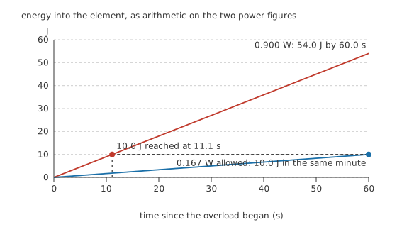
Two straight lines through the origin, and the whole difference between them is the slope.
What that heat leaves behind is a value that has moved. A resistor is sold with a tolerance, and the tolerance is the band it is entitled to sit in:
Worked example — How far outside the band one event leaves the part
The part is 120 Ω, specified at ±1.0 %. Its band therefore runs from 118.8 Ω at the bottom to 121.2 Ω at the top, and anything inside that is the part behaving.
After the overload it measures 122.9 Ω, which is 2.4 % above the marked value and 1.68 Ω clear of the top of the band.
The part still looks right. It conducts, it beeps on a continuity range, and it holds its new value indefinitely. What has changed is the circuit around it: every current it sets is now low by the same fraction, and every voltage it develops as a divider leg has moved with it.
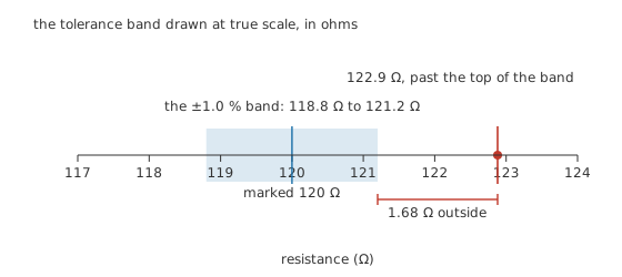
Drawn in ohms at true scale, because the whole failure is a gap of less than two ohms.
That is why a suspect resistor gets measured against its marked value and its tolerance, not against a beeper. Resistor tolerance and precision sets out what the band is promising in the first place.
Engineer
What is actually happening in the element
A film resistor is a thin coat of resistive material on a ceramic rod or chip, with a helical groove cut through the film to trim the value up to its final figure. Current therefore does not cross a uniform cylinder. It follows a long narrow ribbon, and the narrowest part of that ribbon is the hottest part of the component. Damage starts there, local long before it is visible.
Sustained overload works on the film itself. It oxidises, its structure changes, and the effective cross-section of the ribbon shrinks. A thinner ribbon is a higher resistance, so the value goes up rather than down. Carbon composition parts can move either way as their binder changes, but on the film parts that dominate modern boards the upward drift is what to expect. Resistor types and construction covers what each family does under abuse.
A pulse is a different failure
An illustrative single pulse of 4.00 kW lasting 10.0 ms deposits 40.0 J, by the same energy arithmetic as Layer 2. That is not much energy: the same part at its 0.25 W rating would take 160 s to pass it.
The rate is what does the damage. The peak is 16000 times the continuous rating, and none of that heat reaches the leads or the board before the film has to hold it, so the narrow ribbon can crack or lift off the ceramic while the body is still cool enough to touch. Both figures are arithmetic on numbers chosen for this lesson, not limits published for a real part. Pulse-withstanding families exist for this duty and publish their own single-pulse curves, and a standard governs how those curves are measured.
Drift accumulates
Repeat the event and the movement adds up. One 40.0 J pulse moved the part by 2.4 %, which on a straight line is 0.0600 %/J per joule, and on that model the part leaves its ±1.0 % band after only 16.7 J. Real parts obey no single law; the line below is straight so the arithmetic stays visible.
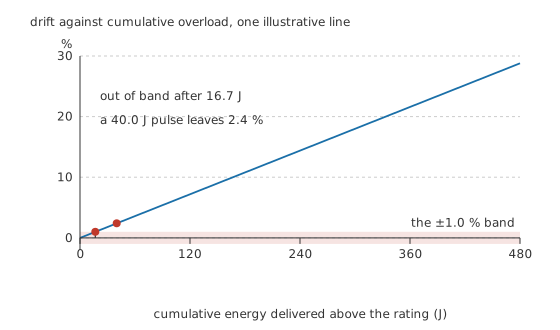
The band is crossed a long way before the first pulse has finished delivering its energy.
Heat that comes back, and heat that does not
A resistor also moves with temperature while it is merely warm, and that shift returns when it cools.
With an illustrative coefficient of 0.000200 per degree, two hundred parts per million, an element 100 °C above room temperature reads 122.4 Ω. That is almost the same number as the 122.9 Ω the overload left behind, and the two are nothing alike. The first goes away when the power does. The second is what the part is now.
Failures that owe nothing to heat
Moisture reaching the film through a cracked coating raises the value and keeps raising it. Sulphur in the air attacks the silver in some thick-film terminations and opens the connection between the element and its end cap, so a resistor with a healthy element measures open. A chip resistor on a board that flexes cracks in the ceramic rather than the solder, and a cracked chip usually reads open too. Bad joints add resistance in series with a good part and get blamed on the resistor more often than they deserve; soldering basics is where those belong.
The resistor that is meant to fail
Some resistors are fitted to fail. A fusible resistor is an ordinary circuit element in normal service and a deliberate weak point under fault. Take a 10.0 Ω fusible element feeding a 240 Ω load from a 24.0 V rail through 2.00 Ω of wiring:
The loop comes to 252 Ω, the normal current is 95.2 mA, and the element turns 90.7 mW into heat, which is 18.1 % of the 0.50 W package holding it. Short the load and the rail lands across the element and its wiring, with the load out of the loop:
giving 2.00 A and 40.0 W, or 80.0 times the package.
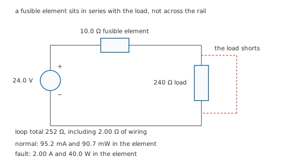
The element is in the load current path. A part placed across the rail would do nothing until it was the fault.
Safety
Nothing above came from overloading a resistor to watch what happened, and there is no reason to do it. Every dissipation, current and drift figure here is arithmetic on the component values stated beside it. A part driven that far past its rating can crack, throw hot fragments, char the laminate under it or ignite a coating, and none of that teaches anything the arithmetic did not.
A failed resistor is not a safe object. One that has gone open leaves the full supply standing across the gap, and one that has drifted high is still a conductor at whatever potential it was wired to. Isolate the equipment, let any stored energy discharge, and confirm with a multimeter rather than a finger.
Where a resistor is a designed sacrifice, its replacement is a specification rather than a value. Fit an ordinary part of the same resistance in place of a fusible one and the board looks identical while the protection has gone. The general practice for working on live equipment is set out in electrical safety fundamentals.
Professional
Designing for the way it will fail
A resistor that fails open is usually the polite outcome. The current stops, the circuit goes quiet, and nothing downstream is fed anything it cannot take. That is the reason a resistor gets chosen as the deliberate weak point in a supply path in the first place.
It is not universally polite. A pull-up that opens leaves a logic input floating rather than defined, and a floating input can oscillate and drive whatever it controls (pull-up and pull-down resistors). A bleeder across a capacitor bank that opens leaves the bank charged after the equipment is switched off, which is the failure nobody notices until they reach in. A gate resistor that opens leaves a power device with no controlled drive. At those nodes the safe-looking failure is the dangerous one, and the design question is not whether the part fails open but what open means there.
The map of end states is worth carrying around. On a logarithmic ohms axis the drifted values sit almost on top of the marked one: the whole span from 120 Ω to a badly cooked 177.6 Ω is 0.170 of a decade, while an open circuit is several decades away in one direction and a short several in the other. Shorted resistors are rare, and where one turns up the explanation is usually something else in the same place, such as solder bridging the part, a flashover across the body or a carbonised track under it.
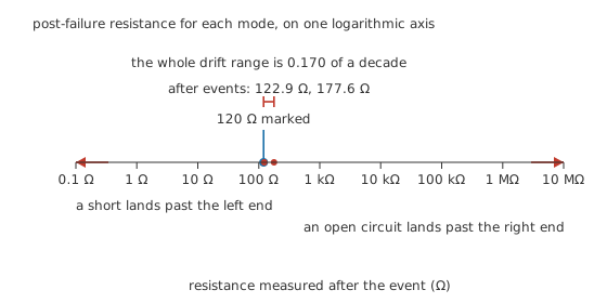
The failure everybody pictures and the failure that happens are five decades apart.
Diagnosis follows from that map. Measure out of circuit, or with one end lifted, because anything in parallel on the board reads back through the part; in-circuit testing is the longer answer. Compare against the marked value and its tolerance rather than against a continuity beep, since a part 48.0 % high passes continuity and fails the circuit. Then read the board: discolouration, a lifted coating, charring on the laminate or a smell all say the part was overloaded, which means something upstream chose to deliver that power, and swapping the resistor alone leaves the cause fitted.
The catalogue answer to most of this is a part built for the abuse rather than a larger version of the wrong part. Fusible and anti-surge families open cleanly and without flame. Pulse-withstanding types spread the current over a film that has not been trimmed to a narrow ribbon. Wirewound parts absorb energy that would destroy a film part of the same continuous rating. A varistor takes surge energy no ordinary resistor should be asked to touch, and the current-sense resistor has a vocabulary of failures of its own, most of them at the terminations. Choosing the right resistor turns all of it into an order of questions, and the resistor introduces the component itself.
Common mistakes
- Testing a suspect resistor with a continuity beeper. A part half again its marked value beeps exactly like a good one. What finds a drifted resistor is a measurement against the marked value and the tolerance band.
- Replacing the resistor and stopping there. A part that overloaded was fed too much power by something else, and the something else is still on the board.
- Reading a resistor in circuit. Parallel paths put their own resistance across the part, so a good reading proves less than it looks and a bad one may not belong to the part at all.
- Substituting an ordinary part for a fusible one. The resistance matches, the board looks right, and the designed weak point has quietly gone.
- Assuming the failure will be an open circuit. Most are. A pull-up, a bleeder or a gate resistor that opens does something worse than stop working, and those nodes need the question asked deliberately.
Frequently asked questions
Do resistors fail open or short?
Open, nearly always. The element degrades until the conducting path breaks, or a termination lets go, and the part measures as an open circuit. A resistor that measures as a short usually has something else across it: solder bridging the pads, a carbonised track underneath, or a flashover path across the body left by a surge.
Why does an overloaded resistor read higher than its marked value?
Because the damage removes conducting material. On a film part the resistive layer is a narrow trimmed ribbon, and heat oxidises it and thins it, which raises the resistance of the path. Carbon composition parts can move either way as their binder changes, but upward is the direction to expect from the film types on modern boards.
Can a resistor be damaged without looking damaged?
Easily. A shift of a few per cent leaves no mark at all, and a part that has taken a single fast pulse can be cracked internally with an intact body and coating. Discolouration means an overload happened, but the absence of discolouration means nothing either way.
Is a discoloured resistor always faulty?
Not necessarily faulty, but always worth investigating. Some parts brown gently over years of running near their rating without ever leaving tolerance. What the discolouration reliably tells you is that the part has been hotter than the designer intended, so measure it and then work out what was delivering the power.
What is a fusible resistor, and can I fit a normal one instead?
It is a resistor built to open safely and predictably when it is grossly overloaded, used where a designer wants a fault to stop rather than spread. No, not with an ordinary part. The resistance is the easy half of the specification; the behaviour on the way to failing is the half you would be throwing away.
Do resistors wear out if they are never overloaded?
They drift slowly. Heat cycling, humidity and age move the value a little over years, which is why long-term stability is its own specification on precision parts. In most circuits the movement is far too small to matter; in a reference divider it is one of the numbers the design has to survive.