
Quick Answer
A pull-up or pull-down resistor gives a logic input a defined voltage for the times when nothing is actively driving it. Without one the pin floats and reads whatever leakage and stray coupling leave behind. The resistor has to be weak enough for a real driver to override, and strong enough to beat the leakage.
Intuition
A disconnected pin is not a zero
Wire a push-button between a logic input and ground, press it, and the input reads low. Release it, and the input reads — what?
The tempting answer is high. The honest answer is that nobody knows, because nothing in the circuit is deciding. When the button is open, that pin connects to a switch that goes nowhere and to nothing else at all. There is no path to the supply and no path to ground. The voltage on it is whatever the last event happened to leave there, nudged around by the leakage in and out of the pin and by whatever the neighbouring tracks are doing.
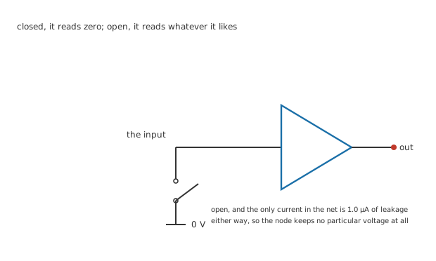
The open blade is the point: the tip of it touches nothing, and neither does the net it leaves behind.
That state has a name — the input is floating — and it is not a third logic level. A logic input promises a definite answer only when it is given a voltage below 0.95 V or above 2.30 V. In between, the part is entitled to report anything, change its mind at any moment, or oscillate. A CMOS input in particular has no opinion of its own: its gate is a capacitor plate, drawing something on the order of 1.0 µA and no more, so it cannot pull itself anywhere.
A pull-up or pull-down resistor is the fix, and it is exactly what it sounds like. Connect a resistor from the pin to the supply and the pin is high whenever nothing else is holding it down. Connect it to ground instead and the pin is low whenever nothing else is holding it up. It is a default, written in hardware, for a wire that would otherwise have none.
Practitioner
The same resistor, and one choice about which end
A pull-up holds the node up at the supply until something drags it down. A pull-down holds it at ground until something lifts it. Past that they are mirror images, and every calculation below runs the same way for both.
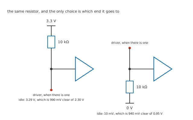
The driver connects at the marked terminal in both, and in both it wins whenever it bothers to say anything.
Take the pull-up. With nothing driving the node, the only current in that resistor is the input's leakage, so
Worked example — The cost of sitting still
An input drawing 1.0 µA through a 10 kΩ pull-up drops V = I × R = 10 mV across it. The pin therefore idles at 3.29 V rather than a clean 3.3 V — a shortfall so small that it leaves 990 mV of clearance above the 2.30 V threshold.
Flip the resistor to ground and the arithmetic is the same drop read from the other end: the pin idles at 10 mV, which is 940 mV below the 0.95 V threshold.
Ten millivolts of error against a volt of margin is why this works at all. The resistor barely has to try.
The interesting half is what happens when a driver does take over. Pulling the node low means the driver has to sink the load's current and the pull-up's on top of it. The pull-up's share never stops while the node is held down.
Worked example — The bill for holding it down
Holding the node at 0.35 V puts 3.3 V minus 0.35 V across the pull-up. Through 10 kΩ that is 295 µA the driver has to swallow, and V² ⁄ R turns it into 870 µW burned in the resistor for as long as the state lasts.
Nothing is burned in the other state. A pull-up costs power only while the line is held low, a pull-down only while it is held high — which is worth knowing before you commit a battery-powered board to thirty of them idling in their expensive state.
Engineer
The window the value has to fit
The value is not a matter of taste. It is trapped between two computed limits, and both of them are worth deriving rather than remembering.
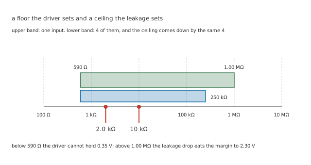
Two limits, three decades of room between them, and both of the lesson's values sitting comfortably inside the narrower band.
The ceiling comes from leakage. Make the resistor big enough and the leakage drop stops being negligible. The largest resistor that still delivers a valid high is the one whose drop exactly consumes the margin: R = (V_cc − V_IH) ⁄ I_leak, which is 1.00 MΩ. Beyond that the pin no longer reads high reliably, and it fails in the worst possible way — intermittently, on the hottest board, because leakage climbs steeply with temperature.
The floor comes from the driver. Make the resistor small enough and the driver can no longer hold the node down. The smallest workable value is the one that asks for exactly the driver's rated sink current: R = (V_cc − V_OL) ⁄ I_OL.
Worked example — Both ends of the window
A part rated to sink 5.0 mA while holding 0.35 V can manage no less than 590 Ω. Against a ceiling of 1.00 MΩ, that leaves a window spanning more than three decades, and the 10 kΩ that everyone reaches for sits near the middle of it on a logarithmic view.
That width is why 10 kΩ has become a reflex, and why the reflex is usually right. It is also why it is worth checking: the window narrows fast once several inputs share a line, once leakage rises with temperature, or once the part doing the pulling is weaker than you assumed.
Professional
The other half of the bill is time
Every wire has capacitance, and a pulled-up line has to charge that capacitance through the resistor before it counts as high. This is the constraint that catches people out, because it is invisible on a schematic and it only bites at speed.
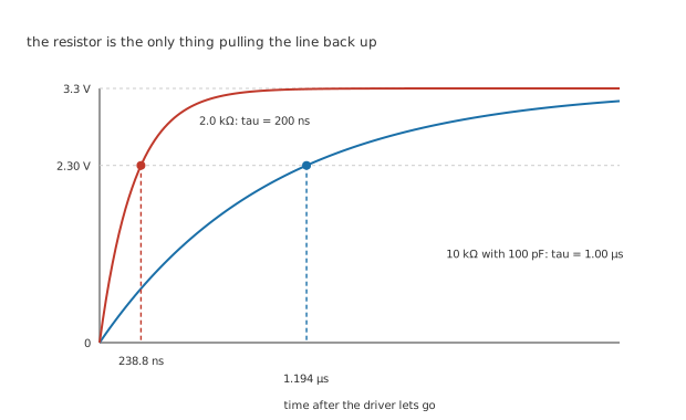
The falling edge is a transistor's work and is fast. The rising edge is the resistor's work alone, which is why the two edges look nothing like each other.
Think of an hourglass with an adjustable neck. The sand always ends up at the bottom; the neck decides how long that takes, and the decision you care about is not when the last grain lands but when the level crosses a particular mark. The pull-up is the neck, the bus capacitance is the sand, and 2.30 V is the mark.
Worked example — When the line has arrived
With 10 kΩ charging 100 pF of line capacitance, the time constant is 1.00 µs. The receiver does not care about the whole curve, only about when it crosses 2.30 V, and that happens at 1.194 µs.
The figure quoted on most datasheets is not that one. It is the time spent between a tenth and nine tenths of the way up, a convention that says nothing about where any particular threshold sits:
Worked example — The number the datasheet would have quoted
The same 1.00 µs gives a rise time of 2.20 µs, which is nearly twice as long as the crossing the logic responds to. Quote the convention and you will over-estimate the delay; quote nothing and you will not notice the line was late.
Drop to 2.0 kΩ and the time constant falls to 200 ns, with the threshold crossed at 238.8 ns. The line is 5.00 times quicker — and the driver now has to sink 1.475 mA instead of 295 µA, which is 5.00 times more, burning 4.35 mW instead of 870 µW. Those two multipliers are the same number, and they always will be: both of them are just the ratio of the two resistors. Speed and standing current are the same dial, and there is no setting that gives you one without the other. Comparators with open-collector outputs live with exactly this trade, and the lesson there plots it out across the range.
One resistor, several outputs
Give several outputs the ability to pull a shared wire down and none of them the ability to push it up, then hang a single pull-up on the line. It now reads low if any one of them says low, and the wiring has done a logic function that nobody had to build.
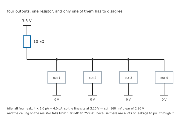
Note where the line stops: at the last device on it, because a rail that runs past its final connection is drawing something that is not there.
Worked example — What sharing does to the ceiling
Idle, all 4 outputs leak at once: 4.0 µA through the same pull-up. The line settles at 3.26 V, still 960 mV clear of 2.30 V, so the high is safe.
The ceiling on the resistor is not. It falls from 1.00 MΩ to 250 kΩ — divided by the device count, exactly.
Two outputs that disagree cost nothing here, which is what the arrangement is for. One says low, the other says nothing, and the line goes low without a fight. Do the same thing with ordinary push-pull outputs and one of them drives the wire up while the other drives it down, straight through both output stages, and the winner is decided by which transistor is stronger rather than by anything you designed.
Common mistakes
- Assuming an unconnected input reads low — it reads nothing in particular. A CMOS input left floating can sit in its own transition region and turn both halves of its output stage partly on, which wastes current and heats the part for no reason at all.
- Fitting a pull-up to a pin that already has one — plenty of parts include weak internal pulls that a configuration register enables. Adding an external one in parallel halves the effective resistance and doubles the standing current, so read the datasheet before fitting one.
- Sizing on the ceiling alone — a value that satisfies the leakage limit can still be too small for the driver to hold down. Both limits bind, always.
- Forgetting that the rising edge is the slow one — a line that behaves perfectly at low speed can fail at high speed purely because the resistor cannot charge the wire in time, and nothing about the schematic will hint at it.
- Ignoring the device count on a shared line — every extra output adds its leakage to the same resistor, and the usable ceiling comes down in proportion.
Frequently asked questions
Is there any difference between a pull-up and a pull-down beyond which rail it goes to?
Electrically they are mirror images. In practice the choice is usually made for you: many logic families and many bus arrangements can only pull down, so the resistor has to go to the supply. Where you genuinely have a free choice, pick the one whose idle state costs less standing current in the state the board spends most of its time in.
Why is 10 kΩ the value everyone reaches for?
Because the usable window is wide and 10 kΩ sits near the middle of it. It is loose enough that the standing current is negligible for most boards and tight enough to beat ordinary leakage with a large margin. It is a sensible default, not a law, and it stops being the right answer as soon as the line is fast or shared by many parts.
Can I use a much larger resistor to save power?
Up to a point, and the point is computable. The leakage ceiling is a hard limit, and long before you reach it the line gets slow and starts picking up noise, because a high-impedance node is an efficient antenna. Large values suit slow, quiet signals such as a configuration pin sampled once at power-up.
Does a pull-down resistor help with switch bounce?
No. It defines the idle state, which is a different problem. A bouncing contact produces a genuine burst of real edges, and the resistor faithfully reports every one of them. Bounce is dealt with in time, by filtering or by software, not by the pull resistor.