
Quick Answer
A resistor's power rating is the heat its body can shed while staying inside its own temperature limit, quoted at one ambient temperature and shrinking above it. Sizing a part means comparing what it dissipates against the rating the derating curve allows at the temperature the part will actually see.
Intuition
The number on the packet is about temperature
A runner who holds a steady pace all morning in cool air cannot hold that pace at noon in August. The legs have not changed. The air has, and with it the rate at which the body sheds the heat it was already making, so the pace that felt comfortable becomes the pace that ends the run.
A resistor is in exactly that position, and its power rating is the cool-morning pace. Every watt that goes in comes back out as heat, and the heat leaves through the leads, the board and the air. While it is on its way out, the element sits above whatever is around it. The rating states how much heat the part can pass along before the element reaches a temperature it was never built to survive, and it is quoted at one temperature of the surrounding air. Warm that air and the same watts leave the element hotter.
Take a 33 Ω resistor carrying 62 mA, which turns 0.127 W into heat, fitted in a package marked 0.25 W. On an open bench that is about half the rating and the sizing question looks closed. Put the same board inside a sealed enclosure that reaches 85 °C and the part is no longer entitled to a quarter of a watt. It is allowed 0.206 W there, and a dissipation that read as 50.7 % of the rating is really 61.6 % of what the part can have.
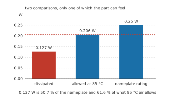
Both comparisons are arithmetic. Only the second one describes a limit the part can reach.
Practitioner
Reading the curve at the temperature you have
Manufacturers publish the rating as a curve rather than a bare number. It holds the printed figure up to a knee, then runs down to zero at an upper temperature in a straight line, and those two temperatures belong to the specification as much as the watts do. The illustrative part used throughout this lesson holds full rating to 70 °C and reaches zero at 155 °C. Neither figure is a constant of nature: both move with the resistor family and with the maker, so read them off the sheet for the part you are actually fitting.
Below the knee the printed figure stands unaltered. Above it, the allowance follows the line:
The slope comes out of the two endpoints and nothing else: 2.94 mW/°C of allowance surrendered for every degree the air rises past the knee. The arithmetic is a single line — what catches people out is that the figure they compared their dissipation against was never the figure that applied.
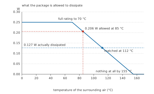
The blue line is what the circuit dissipates. Where it crosses the curve, the part has run out of margin without anything in the circuit having changed.
Worked example — Sizing the part for the air it will sit in
The element is a 33 Ω resistor carrying 62 mA, so it drops 2.05 V and turns 0.127 W into heat.
The package is rated 0.25 W, held to 70 °C and falling to nothing at 155 °C. Inside the enclosure the air sits at 85 °C, past the knee, so the allowance is 0.206 W rather than the printed figure.
Now set the dissipation against each in turn. Against the nameplate it is 50.7 %, which reads like a part working at half its capability. Against the allowance that ambient actually grants, it is 61.6 %, leaving 1.62 times the dissipation in hand. The second comparison is the one the element experiences.
Push the ambient higher and the margin closes from above. The allowance falls to the dissipation itself at 112 °C, and beyond that the part is outside its own curve while the circuit around it has not altered by a milliamp.
The same part on an open bench at 25 °C keeps its full 0.25 W, worth 1.97 times the dissipation. Neither figure is a pass mark on its own; they are the two ends of the range a design has to survive, and a prototype tested only on the cool one has been tested at the easy end.
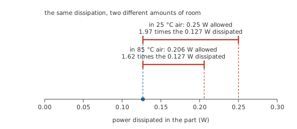
The left end of both brackets is the same dissipation. Only the right end moved.
Engineer
What the sloping line is describing
The slope has a physical origin, and the curve can be read backwards to recover it. Start at the far end of the line. The allowance there is nothing at all, and a part dissipating nothing has no self-heating to speak of, so the element and the air sit at the same temperature — which makes 155 °C the element's own limit, printed on an axis of air temperature only because that is the axis the graph offers. At the knee the element is at that same limit again, this time with the air at 70 °C and the full 0.25 W passing out through it. Divide the difference between those two readings and the thermal resistance from element to air falls out at 340 °C/W; power dissipation works the same reading through on a different circuit.
Everything else follows from that one number. Our 0.127 W lifts the element 43 °C above whatever surrounds it, which puts it at 128 °C inside the warm enclosure and 68 °C on the bench. The dissipation is identical in both cases. Read that way, the whole sloping section states one requirement about the element, which is to stay under its ceiling, and the air is what decides which point on the line meets it.
What the printed figure quietly assumes
The rating is measured, and the measurement carries conditions. A part is tested in a defined situation: free air, or mounted on a board of specified size and copper weight, one part on its own, the air still and the element left to settle. A standard governs how that test is performed, and the data sheet says which conditions its number came from. They are rarely the conditions on your board. Neighbouring parts warm the air the resistor is trying to shed into; a thin track carries less heat out of the terminations than the reference land pattern does; and an enclosure lifts every part inside it above room temperature, which is the whole difference between the two brackets in Layer 2.
How the heat divides between the paths out of the body depends on the package, the copper it lands on and how still the air is. For a small leaded part on an ordinary board, an illustrative split puts 25 % down the leads, 45 % into the board copper and 30 % into the air, and none of that division is fixed by anything except the assembly. Widening the copper at the pads works on the same thermal resistance the derating curve encodes, rather than on the rating.
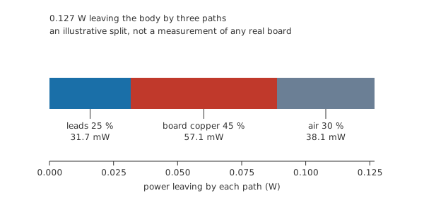
Drawn from that illustrative split rather than from a measurement, to show that the board is usually a real share of the path and not a detail.
Heat also moves the value long before it does anything worse. With an illustrative temperature coefficient of 200 ppm per degree, written here as 0.0002 per degree:
An element 103 °C above room temperature reads 33.68 Ω instead of its marked value, a shift of 2.06 %. That is invisible in a pull-up and unacceptable in a reference divider, and it is a shift that comes back when the part cools. A severe overload leaves one that does not. Resistor tolerance and precision treats the drift properly.
A burst is not its average
The printed rating is a continuous figure, and a resistor has thermal mass, so a short burst is judged by the energy in it rather than the power. Take a 5.0 W pulse lasting 8.0 ms and repeating every 500 ms:
Each burst deposits 40 mJ. At a duty of 1.6 % the train averages 80 mW, comfortably inside the derated allowance, while the peak stands at 20 times the continuous rating.
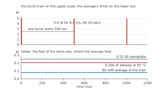
Two vertical scales for the same train, because the peak and the average do not fit on one.
The average clears the continuous rating, and the burst still has a limit of its own. The element has to survive the temperature each pulse creates in it locally, before the heat has spread into the leads or the board at all, and parts built for that duty publish their own curves for it. A burst can kill a resistor whose average dissipation never came near the rating. If the circuit can produce surges, that curve is the number to design against instead of the continuous one, and pulse-withstanding and wirewound constructions exist because ordinary film parts kept failing the job.
Safety
A part comfortably inside its rating can still be too hot to touch. The 128 °C element temperature above is arithmetic on the derating figures and the dissipation, not a measurement, and nothing here was obtained by putting a finger on a resistor. Anything near that temperature will burn skin on contact and can scorch laminate or the insulation of a wire lying against it.
Use a non-contact thermometer or a thermal camera on a part you suspect, and remove power before touching anything. There is no version of this lesson that involves overloading a resistor to watch it fail: an overloaded part can crack, spit hot material or char the board under it, and the useful information was available from the arithmetic first. The general practice for working on live equipment is set out in electrical safety fundamentals.
Professional
Choosing a part rather than a number
Dissipation follows the resistances, so putting parts in series shares the heat only when the parts match. Two of our 33 Ω resistors in series carry the same 62 mA from a 4.09 V supply, and each takes 0.127 W. Split the same 66 Ω total into 10 Ω and 56 Ω instead, at the same current, and the smaller part takes 38.44 mW while the larger takes 0.215 W. That is 18.7 % of the allowance for one of them and 104.6 % for the other, which is past it, in a pair whose total dissipation has not changed at all.
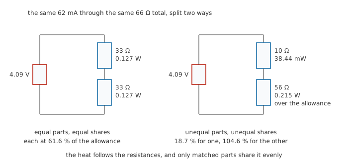
Splitting a resistance to spread the heat only works if the split is even.
Most design offices do not work to the derated figure either. The common habit is to hold continuous dissipation at half of it or less, which for this part in this enclosure means 0.103 W. Our 0.127 W clears the derated rating with room to spare and misses that house rule, and the useful response is to say out loud which of the two the design is being held to rather than quietly taking whichever it passes. The spare half is not superstition — it covers the distance between the board that was tested and the board that shipped.
Heat is not the only limit on the part. A resistor carries a maximum working voltage specified independently of its watts, and a high-value part across a high voltage can be voltage-limited long before it is anywhere near power-limited. Divider chains across high rails need that figure checked element by element, and the usual answer is more elements in series rather than one larger one.
When the arithmetic says no, the choices are ordinary. A physically larger package sheds heat through more surface and a shorter thermal path into the board, and SMD package sizes sets the ratings against the outlines that carry them. A different construction changes what the part tolerates as well as what it dissipates, and resistor types and construction covers which family suits which abuse. More copper at the pads, or a part lifted out of the still pocket of an enclosure, buys watts for nothing. Where the power is large enough to be worth removing deliberately, the part gets a heatsink, or the design moves that energy somewhere it does not have to be burned.
Package availability then pulls against the value. Preferred values and package sizes are separate catalogues, and the E-series value nearest your target may not be stocked in the size the heat demands. Choosing the right resistor turns that trade into a working order of questions, and resistor failure modes describes what the part does when the answer was wrong.
Common mistakes
- Comparing dissipation against the printed rating instead of the derated one. The nameplate figure applies at one ambient. Above the knee the part is entitled to less, and the comparison that matters uses the smaller number.
- Treating the knee and the zero point as universal. They belong to a family and a manufacturer, and a part from a different series with the same watts on it can derate from a different temperature entirely.
- Averaging a pulse train and stopping there. The average tells you whether the part cooks slowly. The energy in one burst tells you whether the element survives the burst, and a part can pass the first test and fail the second.
- Fitting a bigger package and assuming the problem has gone away. A larger part sheds more heat only if the board and the air let it, and dropped into the same still pocket on the same two thin tracks, much of the extra rating stays on paper.
- Assuming a series pair halves the heat in each part. It splits the heat in proportion to the resistances, so an uneven split concentrates it in the larger element rather than spreading it.
Frequently asked questions
What does a resistor's power rating actually promise?
That the element will stay below its own maximum temperature while dissipating that much heat, provided the air around it is at or below the temperature the rating was quoted at, and provided the part is mounted the way the test assumed. It is a thermal statement rather than an electrical one, and the same part carries a separate maximum working voltage besides.
Why does the rating fall as the surroundings get warmer?
Because the element's own maximum temperature is a constant and the air underneath it is not. Self-heating lifts the element above the air by an amount that follows the dissipation, so the gap between the air and that ceiling is the entire budget the part has to work in. Warm air spends part of that budget before the resistor has dissipated anything.
Does a smaller package of the same value run hotter?
For the same dissipation, yes. A smaller body offers less surface and shorter terminations, so heat leaves it less easily and the element climbs further above the air. That difference is precisely what the two packages' different ratings encode, so substituting a smaller part for the same resistance reopens the sizing question rather than leaving it alone.
Can I fit a 1 W resistor where a 0.25 W one is specified?
Electrically yes, and it will run cooler. Watch the physical size and lead spacing, whether the larger body blocks airflow to its neighbours, and, in fast or radio-frequency circuits, the larger part's higher parasitic inductance and capacitance. A wirewound part substituted for a film one changes the frequency behaviour as well as the heat.
How do I know how hot a resistor is actually running?
Work it out rather than touch it. Ambient plus dissipation times the thermal resistance implied by the derating curve gives a usable estimate, and a non-contact thermometer or thermal camera confirms it without contact. A part that has discoloured or scorched the board under it has already told you the answer.