
Quick Answer
Power dissipation is the rate at which a circuit element converts electrical energy into heat, equal to the voltage across the element multiplied by the current through it. In a resistive network the total dissipated always matches what the source delivers, but the share each element takes is uneven, and every element is judged against its own rating.
Intuition
Twice the voltage, four times the heat
Heat is the only thing a resistor makes. Whatever electrical energy goes in comes out as warmth in the body of the part, and it spreads from there into the leads, the board underneath and the air around it. While that heat is on its way out, the resistor sits above the temperature of its surroundings, and how far above is what this lesson works out.
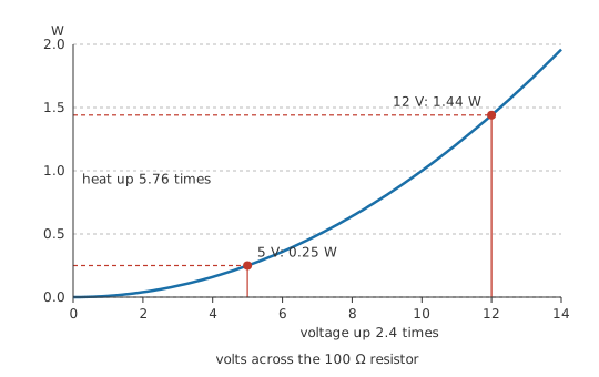
Heat climbs faster than the drive that produces it. Put 5 V across a 100 Ω resistor and it produces 0.25 W of heat, which the smallest common part handles without complaint. Raise the supply to 12 V and the same resistor is making 1.44 W. The voltage rose by a factor of 2.4 and the heat by 5.76, because power follows the square of the voltage across a fixed resistance.
Add a second resistor and the question changes to where the heat lands. In a circuit built from a source and resistances, everything the source delivers ends up as heat somewhere in the network — the totals match, always — but the division between elements is nothing like equal. Two resistors in the same circuit can be producing heat in a ratio of ten to one, and that ratio says nothing about which of them is in trouble. Trouble is settled by how much heat each one was built to shed.
Practitioner
Working out each element's share
The power an element turns into heat can be had from any two of the three quantities that describe it. The general statement uses the two that every two-terminal element has, whatever it is made of:
For a resistance, Ohm's law supplies whichever of those two you did not measure, and that yields the pair of forms most bench work runs on:
All three are one statement written three ways, and they agree to the last digit. They differ only in how much has to be known before you can use them.
For a network, the routine follows the shape of the circuit. Collapse it by series and parallel steps until a single resistance faces the supply, take the total current from that, then expand back outwards, recovering the voltage across each series element and the current in each parallel branch as you go. Every element ends the expansion with both of its own quantities in hand, and each dissipation is then a single line.
Worked example — A three-resistor network, element by element
A 20 V supply feeds 80 Ω in series with a parallel pair, 200 Ω alongside 300 Ω.
Start by collapsing it. The pair in parallel is 120 Ω, which with the series element makes 200 Ω across the supply, so the supply pushes 100 mA. That current crosses the series element and drops 8 V there, leaving 12 V across the pair. The pair divides that between 60 mA and 40 mA.
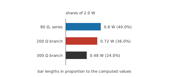
Every element now has a known current and a known voltage, so each can be taken with whichever form is already to hand. The series element's current came first, so I²R gives 0.8 W. The parallel branches share a voltage, so V²/R applies to each of them in turn: 0.72 W and 0.48 W.
Those three come to 2.0 W, against a supply putting out 2.0 W, so the account closes.
The shares themselves say more. The three elements take 40 %, 36 % and 24 % of the total, uneven though not startlingly so. Set each against what its part can shed:
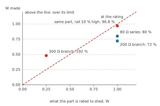
- series element: 0.8 W in a 1 W part, or 80 % of rating
- first parallel branch: 0.72 W in a 1 W part, or 72 % of rating
- second parallel branch: 0.48 W in a 0.25 W part, or 192 % of rating
The element making the least heat is the only one past its limit, and it is past by nearly a factor of two. The third resistor will run hot enough to shift its own value long before the totals stop agreeing.
That closing total told you less than it appeared to. It closes by construction: the currents came from the same resistances the powers did, so the sum can only agree. As a check on the arithmetic it is worth having, while the question of whether the circuit survives is one it never addressed. That question gets answered one element at a time, against that element's own power rating at the temperature it will see in service — a figure that shrinks as its surroundings warm.
Engineer
What squaring does to an error
Each form takes a particular pair of quantities, and both members of that pair have to belong to the element itself rather than to the circuit around it. Reach for I²R in the network above with the supply's 100 mA in place of the branch's 40 mA, and the third resistor appears to be turning 3.0 W into heat where the truth is 0.48 W. The wrong figure is larger by a factor of 6.25, and it arrives without an arithmetic mistake anywhere along the way.
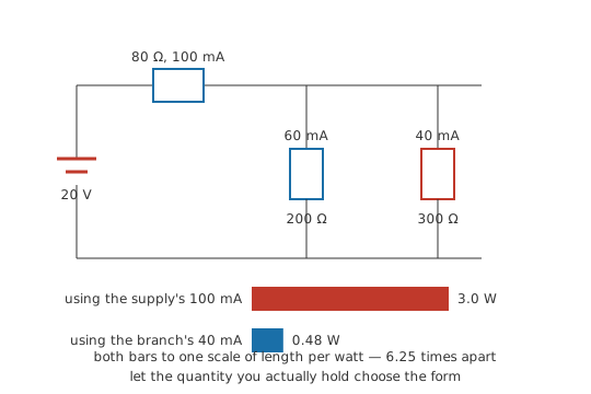
The habit that prevents it is to let the known quantity choose the form. Where the current through the element is the figure you hold, use I²R, and where it is the voltage across the element, use V²/R. If you hold both and they disagree, something upstream of the power calculation has gone wrong, and the dissipation figure is the smaller of your problems.
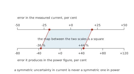
Both working forms are quadratic — I²R and V²/R alike — which changes how measurement error travels. A current reading 20 % above the true value yields a power figure 44 % above the true value, since the excess is squared along with the current. The same error the other way understates power by 36 %. The two figures differ, and the asymmetry runs the unhelpful way: a symmetric uncertainty in current maps onto an uncertainty in power whose upper tail is the longer one. Shunt tolerance, gain error in a sense amplifier and a reading taken while the circuit was still warming all reach the power figure squared.
The same square rules out a shortcut that works everywhere else. Superposition is the standard handle on a linear circuit with several sources: solve for one source at a time, then add the contributions. It holds for currents and for voltages, and it fails for power. Send 30 mA through a 100 Ω resistor and it dissipates 0.09 W, while 40 mA through the same resistor gives 0.16 W, and the two added come to 0.25 W. Now let both sources act together. The currents superpose to 70 mA, and the dissipation that follows from that current is 0.49 W, almost twice the sum of the separate answers.
The discrepancy comes out of the algebra rather than out of the circuit. The square of a sum of two currents is the square of each plus twice their product, and that middle term — worth 0.24 W here — is what per-source bookkeeping throws away. Where the two contributions oppose each other the cross term is negative and the true dissipation falls below the sum. Either way, per-source power figures have to be discarded rather than added. Superpose the currents or the voltages instead, arrive at the real quantity in the element, and square once at the end. The same caution attaches to any quantity built on a square, RMS values and noise budgets among them.
The totals rule from the opening section is easy to over-read, and it has a boundary. Power in equals power out at every instant only while the network is resistive and settled. A capacitor or an inductor takes energy in and gives it back later, so at any given moment the two totals can differ by whatever is moving into or out of storage, and they close again over a complete cycle. A source can also sit on the receiving end: a second rail being charged by the first absorbs power exactly as a resistor does, and its contribution enters the total with the same sign. Everything in this department is DC and resistive, where the instantaneous statement holds without qualification.
Professional
Sizing a part for the conditions it will meet
Reading a derating curve backwards
A power rating always arrives with an ambient temperature attached, and above that temperature it falls. Data sheets draw this as a derating curve: flat at the full figure up to a knee, then a straight line down to zero at some upper temperature. Knee and endpoint differ between resistor families and manufacturers, so the two figures below describe one example part rather than resistors at large.
Worked example — What two derating figures already tell you
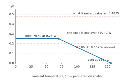
Take the 0.25 W part from the network above, specified to hold its full rating up to 70 °C and to fall linearly to zero at 155 °C.
Read the endpoint first. Zero permitted dissipation means zero self-heating, so the body is sitting at ambient, and the part is being told to stop there. That upper figure is the body's maximum temperature. The body reaches the same limit at the knee with its surroundings at the lower figure, which puts a rise of eighty-five degrees against a quarter of a watt. The part's thermal resistance from body to air is therefore 340 °C/W.
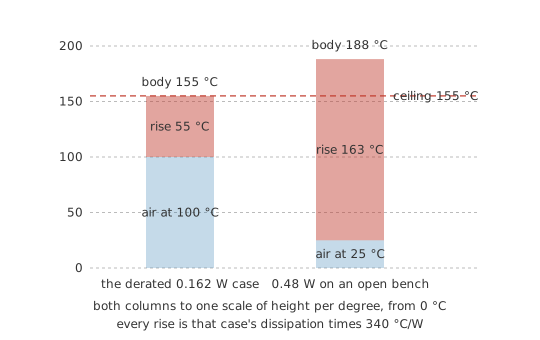
Now take the curve at 100 °C ambient. The straight line between the two specified points allows 0.162 W, which through that thermal resistance produces a rise of 55 °C and leaves the body at 155 °C. It lands on the same ceiling. A derating curve is the set of powers that hold the body at one temperature while the air around it varies, rather than a second specification standing beside the first.
The network's third resistor, in ordinary 25 °C air, gets the same treatment: 0.48 W through that thermal resistance is a rise of 163 °C, which puts the body near 188 °C. That is past the temperature at which the part is rated for nothing at all, and it happens on an open bench with nothing else warming it.
Safety
Every body temperature above came out of published figures and a calculation; no part was touched to obtain one. A resistor anywhere near the rise calculated here will burn skin on contact, and can scorch laminate or ignite nearby insulation. Use a non-contact thermometer or a thermal camera on a suspect part, and remove power before touching anything.
Pulses are a separate specification
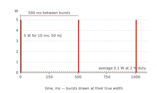
The number on a data sheet is a continuous rating, and a resistor has thermal mass. A short burst raises the element's temperature by an amount set by the energy in the burst more than by the power in it: a 5 W pulse lasting 10 ms deposits 50 mJ, and repeated at 2 % duty it averages 0.1 W, comfortably inside a small part's continuous rating.
Averaging settles only half the question. The element itself has to survive the peak temperature the pulse creates in it locally — before the heat has spread anywhere — and that limit carries its own published curves. Short high-energy pulses destroy parts operating far below their average rating; thick-film chip resistors in small cases absorb them poorly, while wirewound and purpose-built pulse-withstanding types are much better. Where surges are expected, the pulse curve is the specification to read.
How a resistor gives up
Overloaded resistors most often go open. The film cracks or burns through, or the wire melts, and the branch stops conducting. As failures go that one is comparatively kind: an open element passes nothing and takes no further part in the circuit.
Some overloads end differently. A flashover leaves carbonised material behind and carbon conducts; a high-voltage pulse can break down across the spiral or laser cut on the element, which shorts out part of the resistance and leaves a value below the marked one. Either outcome keeps current moving through a part that is no longer what the schematic says, and that is the harder failure mode to find.
Heat moves the value long before it destroys the part. Every resistor carries a temperature coefficient, so a part running hot reads differently while it is hot, and a severe overload leaves a permanent shift that survives cooling. Once a board has been driven that hard, its resistances are no longer the values it shipped with.
Design on the worst case, then check it
Every figure in the worked network came from nominal values, and real rails, resistors and enclosures all depart from nominal. A supply 10 % above its nameplate lifts dissipation everywhere in a resistive network by 21 %, which takes the series element from comfortable to 0.968 W, or 96.8 % of its rating, before a word has been said about ambient temperature or component tolerance.
Stack the worst of each — highest rail, worst-case resistor value in whichever direction raises the heat, hottest ambient the enclosure reaches — and derate the part for that ambient before comparing. A common working ceiling is half the derated rating for continuous operation, and the spare half buys margin against the things nobody modelled: still air where the data sheet assumed a copper pour, or a fan that has stopped. When no ordinary part will do, the remedies are a physically larger element, a heatsink, or a circuit that never burns the power at all.
Common mistakes
- Feeding a power expression a quantity that belongs to the circuit rather than the element. The rail voltage instead of the element's own drop, or the total supply current instead of the branch current. Both produce a confident answer about some other part of the circuit.
- "The powers add up to what the source delivers, so the design is sound." That total agrees whatever ratings were fitted, because it was never a function of them. Every element still has to be checked against its own limit separately.
- Ranking parts by how much heat they make. The one in trouble is the one with the smallest margin over its rating, and in a network of mixed package sizes that is regularly the coolest-running element in the circuit.
- Adding power contributions from separate sources. Superposition holds for currents and voltages only. Squaring a sum is not the same as summing the squares, and the cross term dropped in between can be worth as much as the rest of the answer.
- Treating the printed rating as available at any temperature. It is quoted at one ambient and falls above it, so a part inside a sealed box in a warm room may be entitled to half of what its data sheet prints, or less.
- Sizing on nominal supply and nominal resistance. Dissipation follows the square of the drive, so a tolerance that looks minor on a rail arrives roughly doubled on the heat.
Frequently asked questions
Does everything the supply delivers really turn into heat?
In a circuit made only of a source and resistances, yes: every watt leaving the source is dissipated somewhere in the network, and the two totals match exactly. Add a capacitor, an inductor, a motor or a rechargeable cell and part of the delivered power goes into storage or into mechanical work instead, so the instantaneous totals stop matching even though energy is still conserved over time.
Which form of the power expression should I use?
Use whichever takes the quantities you already hold for that element. With the current through it known, reach for I²R; with the voltage across it known, reach for V²/R; if both are known then either serves, and the two should agree. The forms are algebraically identical, so the choice is only about avoiding an extra step. That extra step, converting between a branch quantity and a circuit-wide one, is where the errors get in.
Can I add up the power each source contributes?
No. Superposition is a property of linear equations, and power is a quadratic function of current or voltage. Solve each source's contribution to the current, add those, then square the result once at the end. Adding the individual power figures discards a cross term that can be worth as much as everything else in the answer.
Why does a resistor's power rating depend on the temperature around it?
The rating is a statement about how hot the element is allowed to get, written in watts. A part sheds heat to its surroundings through a roughly fixed thermal resistance, so the permitted temperature rise, and with it the permitted power, is whatever is left between the ambient temperature and the element's own ceiling. Warm the surroundings and there is less of that headroom to spend.
Is a quarter-watt resistor safe at nearly a quarter of a watt?
On paper, in cool still air, it just about is. In practice the margin has gone: the rating assumes an ambient the enclosure may exceed, the rail may sit above nominal, and the resistor's own value carries a tolerance that can push the dissipation either way. Most designers hold continuous dissipation at or below half the derated figure and treat anything above it as a part wanting a bigger package or a different circuit.