
Quick Answer
Heat leaves a semiconductor through a chain of thermal resistances: the package, the mounting joint, and the heatsink into the air. They add like series resistors, and the junction ends up at the ambient temperature plus the dissipated power multiplied by that total.
Intuition
Three doors between the chip and the room
Heat behaves like current when it is trying to get out of something. It flows from hot to cold, it takes every path available, and each path has a resistance — a number of degrees it costs per watt pushed through it.
A power device has three such paths in series. The package: from the silicon out to the metal tab you can touch. The mounting joint: from that tab into whatever it is bolted to. The heatsink: from the metal into the air.
Add the three resistances, multiply by the watts, and you have how much hotter the silicon is than the room. Add the room's temperature and you have the number that decides whether the part survives.
That single sum is almost the whole subject. The rest is knowing which of the three resistances is worth attacking — and the answer is rarely the one people attack first, because the mounting joint costs nothing but care to improve while a bigger heatsink costs money, weight and space.
The last thing worth saying at this level is that thermal design is slow. A heatsink that takes minutes to warm up takes minutes to cool down, and a circuit switched off five minutes ago can still burn you.
Safety
Heatsinks stay dangerous after the power has gone. The one worked through here sits at 66.2 °C inside a warm enclosure and takes 329 s to fall to a temperature comfortable to hold — the same thermal mass that steadies the junction under load is what keeps the outside hot afterwards. Treat any heatsink as hot until you have checked it. Separately, on many power packages the mounting tab is electrically joined to the device rather than isolated from it, so a heatsink bolted directly to one can be sitting at a live circuit potential. Check what the tab is connected to before touching it and before assuming a shared heatsink is safe to bolt two devices onto.
Practitioner
The chain, and the number it produces
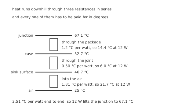
Every resistance in the chain has to be paid for in degrees.
Worked example — One device, one sink, one answer
A device shedding 12 W is bolted to a heatsink that works out at 1.81 °C per watt, through a joint of 0.50 °C per watt, in a package of 1.2 °C per watt.
The three add to 3.51 °C per watt, so 12 W lifts the junction 3.51 °C multiplied by twelve above the air.
Into 25 °C air that puts the junction at 67.1 °C, the case at 52.7 °C and the sink surface at 46.7 °C.
Every one of those resistances is an illustration chosen for this lesson, not a figure read from a datasheet. Package resistances, junction limits and mounting-joint figures are all part-specific and all published by the manufacturer for the part in front of you. The arithmetic is general; the numbers are not, and a design done with borrowed numbers is a design done wrongly.
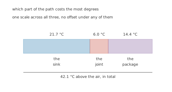
One scale across all three, so the widths really are the degrees.
Look at which segment is which. The heatsink is the largest single contributor, as expected. But the joint and the package together account for more than the sink does, and neither is affected by buying a bigger sink.
Engineer
Choosing a sink, and what the mounting is worth
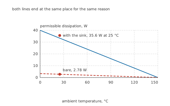
Both lines end at the same place, because that limit belongs to the junction rather than the cooling.
Worked example — What the sink is actually buying
Bare in still air the device has about 45 °C per watt to the room, so 12 W would demand a junction at 565 °C — a number that means the part is destroyed rather than hot.
Working the other way round, an illustrative junction limit of 150 °C allows only 2.78 W from the bare package at 25 °C.
On the sink the same limit allows 35.6 W, which is 12.8 times as much.
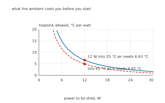
What the ambient costs you before you have started.
Designing usually runs the other way from that worked example. You know the power and the ambient, you pick a junction temperature you are prepared to live with, and the heatsink is whatever is left over.
Worked example — Working backwards to the sink you have to buy
Aim for 125 °C rather than the full 150 °C, because designing to the limit leaves no margin for a hot day or a dirty fan.
At 25 °C that allows 6.63 °C per watt for the sink, after the package and joint have taken their share.
Put the same circuit in an enclosure at 45 °C and the allowance tightens to 4.97 °C, with the junction of the sink already described landing at 86.6 °C. Twenty degrees of ambient has taken a quarter of the heatsink budget, and no amount of heatsink recovers it — only moving the air does.
Worked example — The cheapest improvement in the chain
Bolt the device down dry and the joint goes from 0.50 °C per watt to about 1.4 °C, because metal surfaces touch only at their high spots and air fills the rest.
At 12 W that costs 10.8 °C straight onto the junction, taking it from 67.1 °C to 77.9 °C.
A smear of compound costs nothing and buys as much as a noticeably larger heatsink would. It is the highest-return step in the whole exercise and the one most often skipped.
Professional
Where the heat actually leaves, and how long it takes
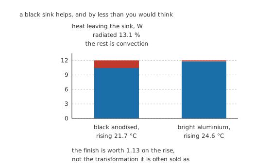
A black sink helps, and by less than the usual claim.
A heatsink's resistance is not a property somebody assigns to it. It is the temperature rise at which the sink sheds exactly the power being put into it, and it comes from two mechanisms working at once.
Worked example — Why anodising is worth less than it is sold as
Convection uses all the fin area at a coefficient of about 8.0 W per square metre per degree, and this sink has a lot of fin area. Radiation only sees the outline, because a fin channel mostly radiates onto the fin opposite and gets it straight back.
Black anodised, at an emissivity of 0.90, radiation carries 13.1 % of the total and the sink settles 21.7 °C above ambient — a resistance of 1.81 °C per watt.
Bright aluminium, at 0.10, radiates 1.7 % and has to run 24.6 °C above ambient to shed the same power.
So the finish is worth a factor of 1.13 on the rise. Real, worth having, and nothing like the transformation it is usually described as — because the geometry that makes a sink good at convection is the same geometry that stops it radiating.
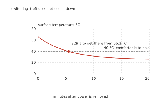
Switching it off does not cool it down.
Worked example — How long it stays dangerous
The sink and the device on it hold about 180 J per degree of thermal capacity. Working against 1.81 °C per watt, that gives a cooling time constant of 326 s.
Starting from the 66.2 °C it reaches inside a warm enclosure, it takes 329 s to fall to something comfortable to hold.
Under load that same slowness is a benefit: a brief overload is absorbed by the metal rather than appearing at the junction.
Five things that decide whether a design works
Air has to be able to get in and out. A sink inside a sealed box heats the box, and the box's own ambient is what the sink is then working against. Convection also needs the fins vertical and unobstructed; a horizontal finned extrusion loses a serious fraction of its rating.
Forced air changes the arithmetic entirely. Even slow airflow raises the convection coefficient several times over, and since convection is doing most of the work here, a small fan can outperform a much larger passive sink. The cost is a moving part that fails.
The tab is often not isolated. On many power packages it is electrically connected to one terminal of the device. Two such devices on one sink are joined together unless an insulating washer is fitted — and that washer adds its own thermal resistance to the joint, which has to go into the sum.
Thermal resistance is a steady-state number. It says nothing about what happens in the first few seconds, where the package's own thermal capacity dominates. A device can survive brief pulses far beyond its steady-state rating, which is what transient thermal impedance curves describe.
Rating a sink from its size is guesswork. The same aluminium extrusion in still air, in a fan stream, mounted flat or mounted upright, spans a wide range. Manufacturers publish curves rather than single numbers for exactly that reason.
Where this arrives next
The same chain governs every power transistor's package, every linear stage that dissipates real watts, and the thermal runaway that happens when a device's own heating raises its current, which raises its heating. In that last case the thermal resistance is not merely a cost — it is inside a feedback loop, and its size decides whether the loop is stable.
Common mistakes
- Adding the resistances wrongly — they are in series from junction to air, so they add. Here 1.2, 0.50 and 1.81 °C per watt give 3.51 °C per watt in total, and 12 W lifts the junction to 67.1 °C.
- Mounting dry — a joint without compound goes from 0.50 to about 1.4 °C per watt, which at 12 W puts 10.8 °C straight onto the junction and takes it from 67.1 °C to 77.9 °C.
- Designing to the junction limit — aiming at 125 °C rather than the illustrative 150 °C leaves margin for a hot day, a blocked vent or a fan that has stopped.
- Ignoring the enclosure's own temperature — the same circuit that needs 6.63 °C per watt of sink in 25 °C air needs 4.97 °C per watt in a 45 °C box, and no heatsink recovers what the ambient took.
- Expecting black paint to transform a finned sink — it is worth a factor of 1.13 on the rise here, because convection uses all the fin area while radiation only sees the outline.
- Assuming a sink bolted to one device is electrically safe to share — many power packages have the tab joined to a terminal, so two devices on one sink are wired together unless insulated.
Frequently asked questions
How do I work out the junction temperature?
Add the three thermal resistances from junction to air, multiply by the power, and add the ambient. Here 1.2 plus 0.50 plus 1.81 gives 3.51 °C per watt, so 12 W into 25 °C air puts the junction at 67.1 °C. Use the manufacturer's figures for your own part; the ones here are illustrations.
Does thermal compound really matter?
More than almost anything else you can do for free. Without it the mounting joint roughly triples, from 0.50 to about 1.4 °C per watt, which at 12 W adds 10.8 °C to the junction. That is as much as a noticeably larger heatsink would have bought.
Is a black heatsink better than a bare one?
Yes, and by about 13 % on the temperature rise here rather than the large factor often claimed. Radiation carries only 13.1 % of the total, because convection uses every square millimetre of fin while radiation only sees the sink's outline — a fin channel mostly radiates onto the fin opposite it.
Why does a heatsink stay hot for so long after switch-off?
Because it stores heat as well as conducting it. This one holds about 180 J per degree, which against 1.81 °C per watt gives a cooling time constant of 326 s. From 66.2 °C it takes 329 s to reach something comfortable to hold.
How much is a heatsink actually worth?
On this example, a factor of 12.8 in permissible dissipation: 2.78 W bare against 35.6 W on the sink, both at 25 °C ambient and the same junction limit. The bare package is not a small heatsink, it is almost no heatsink.