
A transistor package decides how much heat can leave the die, and therefore how much power the device can dissipate before its junction reaches its limit. The calculation is one subtraction and one division: the temperature budget divided by the thermal resistance of the path out.
Intuition
The silicon is the same; the package is not
Two transistors can have identical dies, identical ratings on the first page of a datasheet, and differ by a factor of forty in the power they can actually dissipate. The difference is not in the silicon. It is in what surrounds it.
A package is a heat path first and a mechanical part second. The die makes heat; that heat has to reach the air. Everything between the two — the die attach, the lead frame, the plastic body, the metal tab, the screw, the compound under it, the heatsink — is resistance in that path, and the sum of those resistances is what decides how much power the device can lose before its junction reaches the temperature at which it stops being a transistor.
The arithmetic is short. Take the junction's limit, subtract the temperature of the air, and divide by the total resistance of the path. That is the answer in watts, and there is nothing else in it.
What the choice really comes down to is where you spend the budget. A surface-mount package spends nearly all of it getting from the die into the board. A bolt-down package spends almost none getting to its own tab and hands the problem to a heatsink, where it can be solved with metal.
Safety
Packages that dissipate real power reach temperatures that burn on contact, and they hold them for minutes after the supply is removed — the same thermal mass that keeps the junction steady under load keeps the outside hot afterwards. The metal tab of most power packages is electrically connected to one of the terminals, so a heatsink bolted to it without an insulator is at that terminal's voltage. Every thermal resistance, safe-operating-area boundary and insulator dimension in this lesson is an explicitly invented illustration chosen to make the arithmetic concrete; none is taken from any standard or any real part, and no real device should be sized from them.
Practitioner
What each package can carry
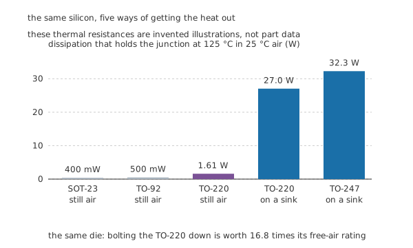
The same silicon, five ways of getting the heat out.
Worked example — The whole calculation, five times
The budget is the same in every case: a junction limit of 125 °C in 25 °C air leaves 100 °C to spend.
In still air, on a board. A SOT-23's path to the air is 250 degrees per watt, so it can lose 400 mW. A TO-92 at 200 manages 500 mW. A TO-220 with nothing bolted to it is 62, so 1.61 W.
Bolted down. Now the path is three resistances in series: 1.2 from junction to case, 0.50 through the mounting, and 2.0 from the heatsink to the air. That is 3.7 in total, so the same TO-220 loses 27.0 W — 16.8 times what it managed on its own.
And the last step is small. A TO-247's junction-to-case is 0.60 rather than 1.2, which takes the total to 3.1 and the dissipation to 32.3 W.
Notice which step is worth the most. Moving from a TO-220 to a TO-247 buys about a fifth. Bolting the TO-220 down in the first place bought sixteen times. The mounting matters far more than the package once the package can be mounted at all.
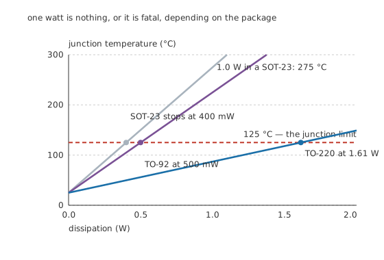
One watt is nothing, or it is fatal, depending on the package.
The same relation drawn the other way up is the one worth carrying around. Junction temperature starts at the ambient and climbs in proportion to dissipation, with the package's thermal resistance as the slope.
Worked example — One watt, three packages
Ask each of the three still-air packages to lose 1.0 W.
The SOT-23's junction would sit at 275 °C — not a working temperature but a destruction temperature, reached in seconds. The TO-92's would sit at 225 °C, which is no better.
The TO-220 sits at 87 °C, comfortably inside its limit, with nothing bolted to it at all.
One watt is the number where surface-mount stops being an option in still air, and it is worth knowing because a watt is an unremarkable amount of power for a circuit to produce by accident.
Engineer
The other limits: the safe operating area
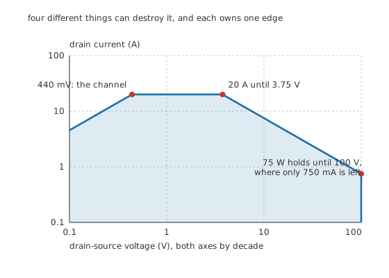
Four different things can destroy it, and each owns one edge.
Power is not the only limit, and the safe operating area is the picture of all of them at once — a region on the voltage-and-current plane inside which the device survives. It has four edges and each is a different failure.
Worked example — Walking the four boundaries
The channel itself, at the left. Below 440 mV the device cannot pass more current than its own 22 mΩ allows at that voltage. This edge is not a limit imposed on the device; it is what the device is.
The current ceiling, along the top. 20 A is set by the bond wires and the metal, not by heat, and it holds until the power limit takes over at 3.75 V.
The power hyperbola, down the right. From there to 100 V the boundary is constant power at 75 W — every point on it is the same product, which is why it is a hyperbola and not a straight line. At the far end only 750 mA is left.
The breakdown wall, at the right. 100 V is a property of the silicon's doping and it does not care what current is flowing.
Why the shape matters: a device is fine at high current or at high voltage and destroyed by a modest amount of both. That is exactly the state a linear regulator lives in, and exactly the state a switch passes through on every transition.
Bipolar devices have a fifth edge that MOSFETs mostly do not. At high voltage and moderate current a bipolar transistor can concentrate its current into a small part of the die, which gets hotter, which attracts more current — secondary breakdown, and it cuts the corner off the power hyperbola well before the power limit is reached. It is the main reason MOSFETs took over linear pass duties.
Professional
The tab is a terminal
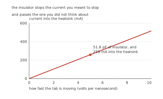
The insulator stops the current you meant to stop, and passes the one you did not think about.
On almost every power package the metal tab is electrically connected to one of the device's terminals — the collector on a bipolar, the drain on a MOSFET. Bolt two of them to the same heatsink and you have wired them together. So an insulating washer goes in between, and it solves the problem it was put there for while creating a quieter one.
Worked example — What the insulator costs
The tab is a plate. A 13 mm by 10 mm tab separated from the heatsink by 100 µm of material with a relative permittivity of 4.5, on a vacuum permittivity of 8.854 p farads per metre, makes a capacitor of 51.8 pF.
Fifty picofarads sounds harmless. Now consider what the tab is doing: on a switching device it is the drain, and it swings the whole supply in nanoseconds.
At 5.0 volts per nanosecond, that capacitance passes 259 mA straight into the heatsink.
The heatsink is usually earthed, and a quarter of an amp of nanosecond-edged current arriving in it is a radiated-emissions problem, a ground-bounce problem, or both. It is why the insulator's thickness and material are an electrical choice as well as a thermal one, and why some designs deliberately let the tab float and insulate the heatsink from everything else instead.
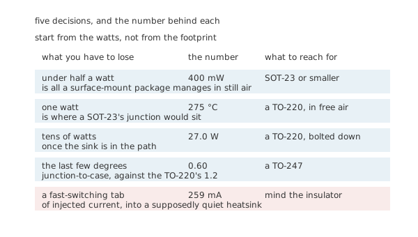
Start from the watts, not from the footprint.
The decision, in order
- Work out the dissipation first. Conduction, switching and quiescent, added up. Everything else follows from it and nothing else can be decided without it.
- Under half a watt in still air, a small surface-mount package is fine. Above 400 mW it is not, and the failure is not gradual.
- Between there and a couple of watts, a leaded package in free air. A TO-220 with nothing attached does 1.61 W.
- Above that, a heatsink, and the package choice becomes secondary. 27.0 W for a bolted TO-220 against 32.3 W for a TO-247 — worth having, but a fifth of the gain the mounting itself delivered.
- Then check the other limits. The safe operating area, the switching transitions the device passes through, and what the tab does to the heatsink it is bolted to.
Two things worth carrying forward
Copper on the board is a heatsink. A surface-mount package's quoted resistance assumes a specific area of copper under it, and doubling that area can change the number substantially. It is the cheapest thermal improvement available, and it is a layout decision rather than a component one.
A datasheet's thermal resistance is a measurement condition, not a property. Junction-to-ambient depends on the board, the airflow and the enclosure; junction-to-case depends on almost nothing and is the only one worth treating as a device parameter. When two parts disagree, check which one is being quoted.
Common mistakes
- Choosing the package by footprint — the dissipation decides it. A SOT-23 that has to lose 1.0 W would sit at 275 °C, and no amount of preferring surface-mount changes that.
- Comparing junction-to-ambient figures between parts — that number depends on the board and the airflow it was measured with. Junction-to-case is the one that belongs to the device.
- Improving the package instead of the mounting — bolting a TO-220 down is worth 16.8 times; upgrading it to a TO-247 afterwards is worth about a fifth.
- Working only to the power limit — the safe operating area has four edges, and a device happily inside its 75 W hyperbola can still be outside its 20 A ceiling or its 100 V wall.
- Forgetting that the tab is a terminal — it carries the collector or drain voltage, so two devices on one heatsink are wired together unless something stops them.
- Treating the insulating washer as purely thermal — 51.8 pF at 5.0 volts per nanosecond puts 259 mA into the heatsink.
Parts used in this topic
Frequently asked questions
How do I work out what a package can dissipate?
Subtract the ambient from the junction limit and divide by the thermal resistance of the whole path. Here that is 125 °C less 25 °C, so 100 °C to spend: 400 mW through a SOT-23's 250 degrees per watt, 27.0 W through a bolted TO-220's 3.7.
Is a TO-247 much better than a TO-220?
Somewhat. Its junction-to-case is 0.60 rather than 1.2 degrees per watt, which on the same heatsink takes the total from 3.7 to 3.1 and the dissipation from 27.0 W to 32.3 W. That is worth having, and it is far less than the 16.8 times that bolting the TO-220 down bought in the first place.
What is the safe operating area telling me?
That four different things can destroy the device and each owns one edge of the region. Below 440 mV the channel's own resistance limits the current; up to 3.75 V the 20 A ceiling does; from there to 100 V a constant 75 W hyperbola does; and 100 V is a wall regardless of current. A device is safe at high current or high voltage, and not at both.
Why does the insulating washer matter electrically?
Because it makes a capacitor between a switching terminal and the heatsink. A 13 mm by 10 mm tab on 100 µm of insulator is 51.8 pF, and at 5.0 volts per nanosecond that passes 259 mA into a heatsink that the rest of the design assumes is quiet.
Can I use a surface-mount package for a watt?
Not in still air. A SOT-23 dissipating 1.0 W would put its junction at 275 °C and a TO-92 at 225 °C, against a 125 °C limit. With a large copper pour and forced air the resistance falls substantially, but the calculation has to be redone for the actual board rather than assumed.
Knowledge check
How much can each package dissipate at a 125 °C junction limit in 25 °C air? (Show answer)
What does bolting the TO-220 to a heatsink change? (Show answer)
Where would a SOT-23's junction sit if asked to lose 1.0 W in still air? (Show answer)
Name the four edges of the safe operating area. (Show answer)
What does the insulating washer do besides insulate? (Show answer)
One email a month from the bench
New circuits, lessons, part guides and calculators, on the first Sunday of each month.