

Quick Answer
A load is any part of a circuit that draws current from a source and converts electrical energy into another form. Connecting a load always changes what the source delivers, because every real source has internal resistance. That change is called loading, and it can be negligible or ruinous.
Intuition
The crank gets stiffer
Turn the handle of a hand-cranked generator with nothing connected and it spins almost freely. Connect one small lamp and you feel a slight drag. Connect five and the handle becomes genuinely hard to turn. The generator is doing the same job throughout. The difference is in how much the things attached to it are asking of it.
Those attached things are the load. Any circuit has a source that supplies energy and a load that takes it, and the load is whatever converts that energy into something else: a lamp into light, a motor into motion, a heater into heat, a chip into computation and heat.
How much current flows is settled by the load rather than by the source. A voltage source offers a voltage; what comes out of it depends on whatever is connected across it. Plug in something demanding and a lot of current flows; plug in something modest and a little does. The source responds to what is asked of it.
The dependence runs in both directions, though. Every real source has to work harder for a heavier load — and working harder means losing more voltage inside itself — so connecting a load changes the very thing the load is connected to. A supply reading exactly 5 V with nothing attached reads slightly less with something attached, and much less with something demanding attached.
Most of the time the change is small enough to ignore, which is why the idea takes a while to notice. Occasionally it is large enough to make a circuit fail or a measurement meaningless, and an engineer learns early to recognise which of the two is in front of them.
Practitioner
Stating a load three ways
A load can be described by its resistance, by the current it draws, or by the power it consumes, and any one implies the other two once the voltage is known. Datasheets pick whichever is most natural: heaters and lamps are quoted in watts, indicator LEDs in milliamperes, terminating networks in ohms.
Worked example — One load, three descriptions
A device is specified as 2 W at 5 V.
Dividing power by voltage gives the current it draws: 400 mA. Dividing voltage by that current gives the resistance it presents: 12.5 Ω.
Those three numbers describe the same load. Which one a datasheet quotes depends on which of them stays constant as conditions change, and for many real loads none of them does.
Calling a load heavy or light is always a comparison. A load is heavy when its resistance is low against the source's internal resistance, and light when it is high, so no threshold in ohms separates the two. The same load can be trivial for a bench supply and impossible for a coin cell.
Loads sitting in parallel add their currents. Each one connected across the same rail draws whatever it draws, and the source supplies the sum. In conductance terms they add directly; in resistance terms the combined load resistance falls as loads appear, which says the same thing in a more awkward form.
Some things count as loads without looking like one. A voltmeter across a node draws a little current, so does a scope probe on a signal, and so does the input of the next amplifier stage. Each of them is designed to be light enough that the current it takes does not matter.
That is why an instrument's input impedance appears on its specification at all. A multimeter has a high input resistance precisely so that connecting it changes the circuit as little as possible. The figure stops being a formality as soon as the circuit's own impedance comes close to it.
Engineer
Loading is a divider
Any real source can be represented as an ideal source in series with a resistance. That is Thévenin's theorem, and it holds for any linear network rather than only for batteries. Attach a load resistance to the model and the two resistances form a divider:
Worked example — How much a load changes the reading
A node has an open-circuit voltage of 3 V and a source resistance of 10 kΩ.
Connecting a load of 10 kΩ — equal to the source resistance — gives 1.5 V, an error of 50 % against the unloaded value. The measurement has destroyed what it was measuring.
Connecting 1 MΩ instead gives 2.97 V, an error of 0.99 %. Between the two connections the source was left exactly as it was. The ratio between the two resistances is the only thing that moved.
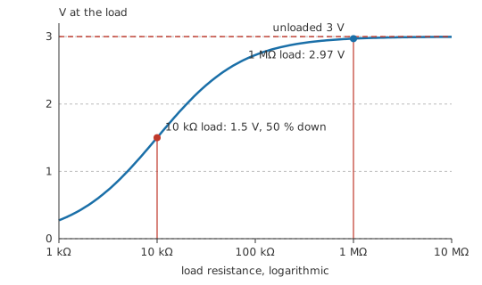
What sets the loading error is the ratio of source resistance to load resistance rather than either value on its own. In practice a load ten times the source resistance costs roughly ten percent, a hundred times costs about one percent, and a thousand times is usually beneath the noise.
High-impedance nodes are where the ratio turns hostile. Photodiode front ends, pH probes, piezo sensors, feedback dividers made of megohms and the gate of a MOSFET are all sources with very high internal resistance, and an ordinary meter across any of them reads substantially low. The remedy is a buffer — an amplifier with a very high input resistance and a low output resistance — and it belongs at the source rather than at the instrument.
A source responds to its load only up to the edge of its capability. Beyond its current limit a supply stops holding voltage, and beyond its compliance a current source stops holding current. A load heavy enough to push a source out of its operating region has stopped merely loading it and started changing what kind of source it is.
Reactive loads move the question from resistance to impedance. A capacitive load draws a surge when the voltage changes and nothing at all when it is steady, while an inductive load resists changes in its current and produces a voltage spike when it is interrupted. On AC, asking how heavy a load is becomes a question about impedance and phase rather than about resistance, and the power delivered depends on both.
Loading is sometimes deliberate. A bleeder resistor across a supply discharges it safely and gives a lightly loaded supply something to regulate against, and a terminating resistor loads a transmission line to match its impedance. Certain regulators carry a minimum-load requirement because they misbehave with nothing connected at all.
Professional
Real loads misbehave in characteristic ways
A constant-power load presents a negative incremental resistance. A switching converter feeding a fixed load draws whatever current it needs to hold its output power, so its input current rises as its input voltage falls.
Drawing 25 W from 12 V means 2.08 A; the same load on a sagging 9 V rail draws 2.78 A. The extra current increases the drop in the supply and in the wiring, which lowers the voltage further. With enough source resistance the process runs away and the rail collapses, which is why upstream impedance and input capacitance are treated as stability questions in distributed power systems as well as efficiency ones.
Many loads draw their largest current in the first instant. Capacitive input filters, incandescent lamps with cold filaments and motors at standstill all take far more at switch-on than in steady state — often by an order of magnitude. A supply, fuse or switch sized on the steady-state figure fails at that moment, which is what soft-start circuits, negative-temperature-coefficient thermistors and sequenced power-up are for.
Switching an inductive load off is the dangerous half of driving it. Interrupting current through a relay coil, a solenoid or a motor produces a voltage spike that can destroy the switching device and generate broadband interference. Flyback diodes, snubbers and clamps exist for this, and omitting them is a reliably destructive shortcut.
Where algebra gets impractical, the load line does the work graphically. Plot the source's voltage-current characteristic and the load's on the same axes, and the operating point is where the two cross. Transistor bias points, the maximum power point of a solar panel and the behaviour of a non-linear load are all found this way.
Testing a supply properly takes a programmable electronic load. It can present constant current, constant resistance, constant power or an arbitrary profile, and step between them in microseconds, which is what measuring a transient response requires. A bank of power resistors tests only the steady state.
Hot-swap and sequencing are both load-management problems. Inserting a live board presents a discharged capacitance to a live rail, which for a moment is a short circuit. Hot-swap controllers limit that inrush, and power sequencing controls the order in which loads appear, because a chip powered from one rail and driven from another can be damaged if the order is wrong.
The worst case is sometimes the lightest load. Some regulators need a minimum load to stay in regulation, a linear current source dissipates most when its load resistance is lowest, and efficiency curves usually fall away at the light end. Verifying a design at full load establishes one end of a range and says nothing about the other.
Common mistakes
- Forgetting that connecting a load changes the source — every real source sags under load, and the sag is proportional to how heavy the load is relative to the source's internal resistance.
- Measuring a high-impedance node with an ordinary meter — when source and meter resistance are comparable, the reading is substantially low. Buffer at the source.
- Thinking loading error depends on absolute resistance — it depends on the ratio of load to source resistance. A megohm load is heavy on a ten-megohm source.
- Sizing a supply, switch or fuse on steady-state current — inrush from capacitors, cold filaments and stalled motors can be an order of magnitude higher.
- Switching an inductive load without a clamp — interrupting the current produces a destructive voltage spike and broadband interference.
- Treating a constant-power load as a resistance — its current rises as the rail falls, which can drive an interaction with the supply that ends in collapse.
Frequently asked questions
What is a load in a circuit?
Anything that draws current from a source and converts electrical energy into another form. Lamps, motors, heaters, chips and even measuring instruments are all loads.
What does loading mean?
The change a load causes in the thing it is connected to. Because every real source has internal resistance, drawing current from it lowers its terminal voltage.
How much load is too much?
It depends on the ratio to the source's internal resistance rather than on any absolute value. A load ten times the source resistance costs roughly ten percent of the voltage; a hundred times costs about one percent.
Why does my meter read low on some circuits?
Because the meter's input resistance is loading a high-impedance node, forming a divider with the source's own resistance. Compare the two before believing the reading, and use a buffer if they are comparable.
What is inrush current?
The much larger current a load draws briefly at switch-on, before it reaches its steady state. Capacitive inputs, cold lamp filaments and stationary motors all show it, and it sizes fuses, switches and supplies.