
Quick Answer
A potentiometer is a resistive track with a sliding contact, the wiper, that divides the track into two resistances whose sum stays fixed. Wire all three terminals and it is an adjustable voltage divider. Wire two and it is an adjustable resistance, called a rheostat. Turning the shaft moves the split, not the total.
Intuition
The same track, two lengths
Press a finger onto a violin string and the string itself does not change. What changes is where it is divided: a short length on one side of the finger, a long length on the other, and the two always adding back to the whole string. A potentiometer does that to a resistance. The track is fixed at whatever value is marked on the body, a contact called the wiper rides along it, and the wiper decides how much of the track lies on each side.
That is why the part has three terminals instead of the two a resistor needs. The outer two reach the ends of the track. The middle one reaches the moving point between them. Take a 47.0 kΩ track with the wiper 30.0 % of the way up from the bottom end: below it lies 14.1 kΩ of track and above it 32.9 kΩ, and those two add back to the marked value wherever the shaft happens to be.
Put 5.00 V across the outer terminals and the split becomes a voltage. The wiper sits at 1.50 V, the supply scaled by the fraction of track underneath it. Turn the shaft and the reading follows the finger.
The same part will also do a second job, and that job throws one terminal away. Connect the wiper and one end only, and what is left in the circuit is a plain adjustable resistance, called a rheostat. The setting that gave 1.50 V as a divider gives 14.1 kΩ as a rheostat. One track, read two ways.
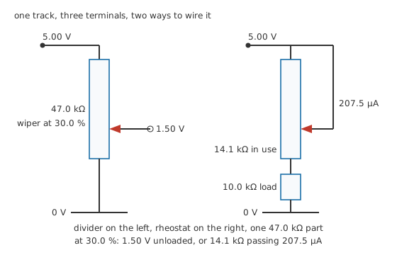
The unused end of a rheostat is tied to the wiper so no section of track is left floating.
Practitioner
Wiring it, and what the taper does
The three-terminal connection is a voltage divider whose two arms move together:
R_2 is the section between the wiper and the bottom end, R_1 the section above it. Their sum is the marked value and does not move, so the denominator is a constant and the output is the supply multiplied by the wiper's position along a linear track. A pair of fixed resistors would need both values changed to shift the tap; here one shaft does it, and one arm grows by exactly what the other loses.
Wired as a rheostat the arithmetic changes, because the track is no longer standing across the supply by itself. The section in circuit is in series with whatever it feeds, and the current through both comes from Ohm's law over their total:
Worked example — The same setting used as a rheostat
A 47.0 kΩ pot has its wiper at 30.0 % of travel, with only the wiper and the bottom end connected. That leaves 14.1 kΩ in the path, feeding a 10.0 kΩ load from 5.00 V.
The two sit in series, so the loop sees 24.1 kΩ and passes 207.5 µA. The load takes 2.075 V of the supply, and the section of track that set the current dissipates 607 µW.
Wind the shaft down to its bottom stop and the track leaves the path altogether, handing the whole supply to the load. Wind it to the top and the entire track is in series. A rheostat sets a current rather than a voltage, and while the load stays connected there is no setting that brings that current to zero.
Nothing so far says the fraction of track under the wiper has to follow the shaft in a straight line. Taper is the name for that relationship, and it belongs to how the track was made rather than to how the part is wired. A linear taper puts 2.50 V at 50.0 % of travel from a 5.00 V supply: half the rotation, half the output. A logarithmic taper holds the output down through the early part of the rotation and lets it climb steeply at the end. The one drawn below reaches 15.0 % of full output at mid-travel, which is 0.750 V, and has still only got to 2.42 V by 80.0 %.
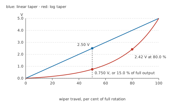
Both curves start and finish in the same place. What differs is where the rotation spends its useful range.
That shape looks perverse until you turn a volume control. Loudness is judged on ratios rather than differences, so a linear track spends most of its rotation in a region the ear already hears as loud, and the whole useful adjustment crowds into the first few degrees. A log taper spreads the audible change evenly along the shaft. The curve above is the ideal exponential law fitted to that one mid-travel figure; production audio parts approximate it with two or three straight segments and a visible kink where they meet, which is close enough for a knob and nowhere near close enough for a calibrated instrument.
Reverse-log parts exist for controls that have to work the other way round. Manufacturers letter their tapers, but the letters do not carry the same meaning in every catalogue, so the curve printed in the datasheet settles it and the code stamped on the body does not.
Engineer
What a load does to the ratio
The rule from Layer 1, output equals supply times travel, carries one condition that has been quiet so far: the wiper has to be carrying no current. Everything the divider expression does depends on both sections passing the same current, and that stops being true the moment anything is connected to the middle terminal.
Connect a load from the wiper to the bottom end and it shares both of its nodes with the lower section, which makes the two a parallel pair. The divider that is really present has that combination as its lower arm.
Worked example — Mid-travel with a load a fifth the size of the track
The 47.0 kΩ track sits across 5.00 V with the wiper at 50.0 % of travel, where it would read 2.50 V with nothing connected.
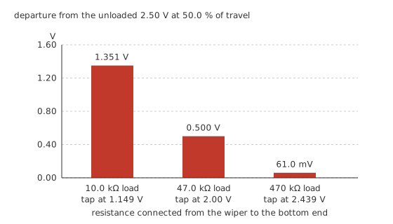
Hang a 10.0 kΩ load on the wiper. That load and the lower section combine to 7.015 kΩ, and the upper section, unchanged at half the track, now divides against that instead. The wiper falls to 1.149 V, which is 1.351 V below where the shaft position says it should be.
Nothing has gone wrong with the part. The divider is doing correct arithmetic on the lower arm it now actually has.
Both arms move as the shaft turns, so the error does not simply grow with travel. Near the bottom the lower section is small, the load barely changes it, and the output is nearly right. Near the top the lower section is large but the upper one has almost vanished, so there is very little resistance left to drop the extra current across, and the output comes back to nearly right again. The damage is worst somewhere in between, and it is not the middle: with a load a fifth the size of the track, the largest departure lands at 74.3 % of travel, where the output sits 1.757 V low, or 35.14 % of the whole supply.
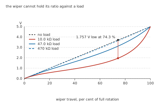
A load does not shift the curve down. It bends it, and the bend is worst well past the middle.
At mid-travel the three loads separate cleanly. The 10.0 kΩ load costs 1.351 V and leaves the tap at 1.149 V. A load equal to the track, 47.0 kΩ, costs 0.500 V for a tap of 2.00 V. Ten times the track, 470 kΩ, costs 61.0 mV and leaves 2.439 V, which most circuits would accept without comment.
There is a tidier way to think about all of this than recomputing a parallel combination for every setting. Looked at from the wiper and the bottom end, the pot is a source with a resistance behind it, which is Thévenin's theorem applied to a divider whose arms happen to be adjustable. That resistance is the two sections in parallel, and it reaches its largest value at mid-travel, where both are half the track: 11.75 kΩ, a quarter of the marked value. Every departure above follows from comparing the load with that figure rather than with the track resistance, which is why the same 10.0 kΩ load that ruins a 47.0 kΩ control would barely register on a track a tenth the size.
The working rule that falls out is a comparison, not a current. A load ten times the pot's own output resistance costs roughly a tenth of the output at the worst setting; a hundred times costs about a hundredth. The absolute size of the load current never enters into it, which is the same trap set out in loading and the reason a meter placed on a high-value divider reads low. Where the following stage is a converter input or anything else with a resistance you cannot pick, the honest fix is a buffer: an op-amp follower between the wiper and the load draws almost nothing from the track and hands the same voltage on at a resistance near zero.
Professional
Living with a real part
Where the heat goes
A pot standing alone across a supply dissipates what any resistance of its value would, and the wiper position makes no difference to the total.
Loading the wiper breaks both of those statements. The sections stop carrying the same current, so the total changes with the setting and the split between the halves stops being proportional. With the 10.0 kΩ load still on the wiper, the whole part burns 556 µW at 20.0 % of travel, 687 µW at 50.0 % and 924 µW at 80.0 %, and the section above the wiper takes almost all of it: 522 µW, then 631 µW, then 785 µW.
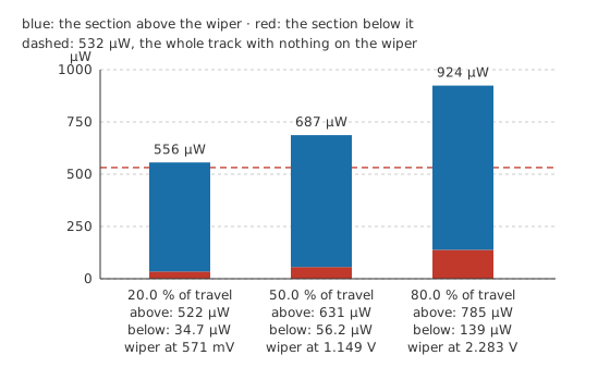
The dashed line is the unloaded figure. Loading moves the total and tilts the split at the same time.
A pot's power rating is written for the whole track, and a rheostat connection ignores that assumption. The section in circuit takes the most power when its resistance matches the load's, which on this part happens at 21.3 % of travel: 250 µA flowing produces 625 µW in that section, and it lands in 4.70 times less track than the rating was written against. Manufacturers discount the rating for rheostat use on exactly that account, and by how much is their business rather than arithmetic's. The general treatment is in resistor power ratings and derating; the figures above are arithmetic on the values named here, not measurements of any real part.
The ends are not zero
Turn the shaft to a stop and the wiper does not arrive at the terminal. A small end resistance separates the two, part contact and part the lead-out from the track, and the datasheet specifies it. Take an illustrative 100 Ω at each end of this track. What is left to move across is 46.8 kΩ, and the three pieces in series come back to the marked value:
which returns 47.0 kΩ, as it must. The cost is 0.213 % of the range unreachable at each stop, so from 5.00 V the output bottoms out at 10.6 mV instead of at ground and tops out at 4.989 V instead of at the rail.
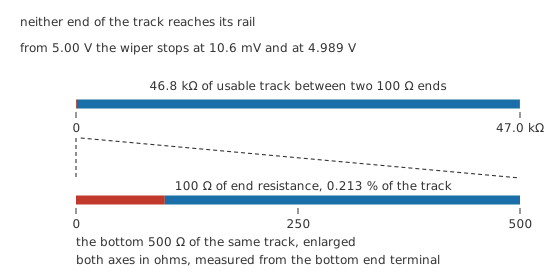
For a volume control that hardly matters. For a circuit trimmed to exactly zero it matters a great deal, and the answer is usually to put the pot in series with fixed resistors so its whole range lands on the small window that needs adjusting.
The wiper is a sliding contact
Everything above treats the wiper as a perfect connection. It is metal pressed against a track, so its resistance varies with position, with contact force, and with whatever has settled on the track since the part was made. That variation is why a pot carrying DC through its wiper crackles when turned, and why a well-designed audio circuit keeps DC off the wiper.
Track material decides most of the rest. Carbon film is cheap and drifts; cermet holds its value better and takes more heat; a conductive-plastic track is smooth and quiet; a wirewound track has the lowest temperature coefficient of the group and cannot be set between turns, so its output moves in steps rather than continuously. Those are the same trade-offs set out for fixed parts in resistor types and construction, with a moving contact added on top.
The mechanical side has its own specification. Manufacturers rate a pot for a number of operating cycles, and a trimmer set once in production is rated for far fewer than a panel control turned daily. Multi-turn trimmers trade rotation for resolution. Where a setting has to survive vibration or be reproduced exactly on a thousand boards, a digital potentiometer replaces the track with a switched resistor ladder and the shaft with a serial interface, at the cost of a supply, a limited number of steps, and a maximum voltage its switches will pass.
Common mistakes
- The unloaded ratio quoted for a wiper that is driving something. The real lower arm is the section in parallel with whatever hangs on the wiper. Combine them first, then divide, and check the worst setting rather than the middle.
- Choosing the track value by habit rather than against the load. The comparison that matters is the load against a quarter of the track value, which is the largest resistance the wiper can present.
- Leaving the unused end of a rheostat floating. Tie it to the wiper so no section of track is left as an unterminated stub picking up whatever passes.
- A pot used as a rheostat at its full power rating. The rating assumes the whole track is sharing the heat. A partial setting concentrates the same watts in a fraction of it.
- Expecting the ends of the travel to reach the supply rails. End resistance holds the output short of both, and a circuit that has to reach exactly zero needs fixed resistors around the pot rather than a better pot.
Frequently asked questions
What is the difference between a potentiometer and a rheostat?
The part is usually the same; the wiring is not. A potentiometer uses all three terminals and produces an adjustable voltage from a fixed supply. A rheostat uses the wiper and one end, and produces an adjustable resistance in series with whatever it feeds. Wiring a three-terminal pot as a rheostat is normal practice, with the unused end tied to the wiper.
Why does my potentiometer output not match the position of the knob?
Almost always because something is drawing current from the wiper. The lower section and the load form a parallel pair, and the divider works on that combination rather than on the track alone. Compare the load with a quarter of the track resistance: if it is not ten times larger, the sag is arithmetic rather than a fault.
Should I use a linear or a logarithmic taper?
Linear where the output is meant to track the shaft, as in a position sensor, a set-point control or a bias adjustment. Logarithmic where a human ear or eye is judging the result, as in volume and brightness controls, because perception follows ratios and a linear track would crowd the whole useful range into a few degrees of rotation.
What value potentiometer should I choose?
Work down from the load. Pick a track resistance low enough that a quarter of it is small against whatever the wiper feeds, then check the standing current and the dissipation at your supply. The two requirements pull in opposite directions, and a buffer after the wiper removes the first entirely.
Why does a volume control crackle when I turn it?
The wiper is a sliding contact whose resistance varies as it moves. If DC flows through it, every variation becomes a voltage step, and a worn or dirty track turns that into audible noise. Cleaning helps a contaminated track, but a circuit that puts DC across the wiper keeps making the noise however clean the part is.