
Quick Answer
Meter loading is the change a measuring instrument causes in the circuit it is measuring. A voltmeter draws some current and pulls the reading down; an ammeter adds some resistance and reduces the current it reports. In both cases the error is set by one ratio of resistances.
Intuition
The instrument joins the circuit
A meter is not a passive observer. The moment its probes touch, it becomes another component in the circuit, and the circuit responds to it exactly as it would to any other component that had just been soldered in.
A voltmeter is a resistance placed across whatever it is reading. Current flows into it, and that current has to come from somewhere: it comes out of the circuit, and the voltage falls a little. An ammeter is a resistance placed into a loop, so the loop's total resistance rises and the current the meter reports is smaller than the one that flowed before it arrived.
Both effects are real physics rather than instrument error. The reading is a correct reading of the circuit that exists while the probes are attached. What it is not is a reading of the circuit you were interested in.
A survey behaves the same way. Asking people what they think about something they have never considered creates the opinion as much as it records it, and a survey that changes what it is measuring gives an honest answer to a question that only existed once it was asked.
The size of the effect is what matters in practice, and it comes down to one comparison. Put a resistance across a source and what matters is how it compares with the source's own. Put a resistance into a loop and what matters is how it compares with the loop's. Everything else in this lesson is that comparison, made numerical.
Practitioner
Sizing the error before you take the reading
Every loading question is answered from two numbers: the resistance of the instrument, which is on its datasheet, and the resistance of what you are measuring, which comes from the schematic.
For a voltmeter, the relevant circuit resistance is what the source looks like from the two points being measured. For a simple divider that is the two arms in parallel:
and the reading follows from putting the meter's resistance in parallel with the lower arm and dividing again:
Worked example — The same tap, read by two instruments
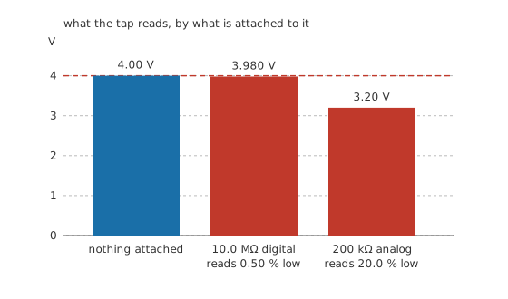
Two 100 kΩ resistors across 8.00 V put their tap at 4.00 V with nothing attached, and the source resistance seen at that tap is 50.0 kΩ.
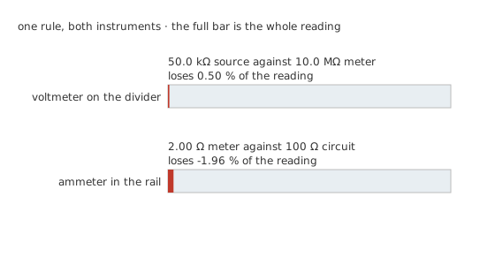
Attach a digital meter of 10.0 MΩ. The lower arm becomes 99.01 kΩ, the divider loses a little of its symmetry, and the reading is 3.980 V, low by 0.50 %. On most work that is nothing at all.
Attach an older analog meter instead, whose resistance on this range works out at 200 kΩ. Now the lower arm becomes 66.67 kΩ, and the meter reports 3.20 V, low by 20.0 %. Nothing about the instrument is faulty and nothing about the divider has failed. A fifth of the reading has gone into supplying the meter.
The current tells the same story more directly. With the analog meter attached, 48.0 µA arrives at the tap from the upper arm and splits between the two paths available to it:
leaving 32.0 µA to continue through the lower arm while 16.0 µA goes into the instrument.
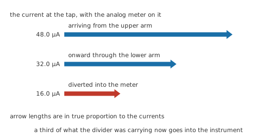
A fifth is not a small error. Here is where it went: not into the instrument's inaccuracy, but into the current the instrument had to be given before it could report anything at all. Every voltmeter ever built takes some.
The working habits that follow are short. Know your meter's input resistance, and know it for the range you are on, because an analog meter's varies with the range while a digital one's usually does not. Estimate the source resistance from the schematic before probing a high-impedance node. Where you have two meters, take the reading with both: agreement is evidence, and a disagreement tells you which one is loading.
Engineer
Putting a number on the disturbance
The fraction of the reading that loading costs depends on nothing but the ratio of the two resistances. For a voltmeter of resistance the same as the source it sits on, half the reading disappears. Ten times larger and the loss is around a tenth of that; a hundred times, a hundredth.
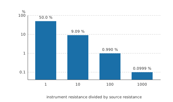
The design rule follows directly: the instrument has to be large against the source by whatever factor your tolerance demands. A hundred to one buys about one per cent; a thousand to one buys a tenth of that. It also says the ratio is what matters and not the absolute figures, so a megohm meter on a kilohm node is in exactly the same position as a gigaohm meter on a megohm one.
The ammeter runs the same rule upside down
Take a 3.30 V rail feeding 100 Ω, which draws 33.0 mA. Insert an ammeter of 2.00 Ω and the loop resistance rises, so the current becomes 32.4 mA, an error of -1.96 %.
The fraction lost is the meter's own resistance measured against the circuit's, exactly as before, with the comparison the other way up. A voltmeter wants to be much larger than what it is placed across; an ammeter wants to be much smaller than what it is placed in.
The ohmmeter's version of the same problem
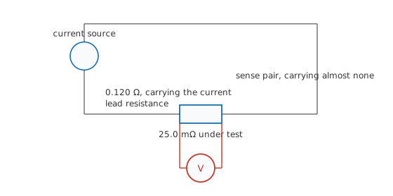
An ohmmeter drives current through the part and reads the voltage that results, so any resistance in the current path is measured along with the part. Against a 25.0 mΩ resistance, 0.120 Ω of lead and contact resistance gives a reading of 0.145 Ω, wrong by 480 %.
The cure separates the two jobs. One pair of leads carries the current, and a second pair senses the voltage at the ends of the part itself. The sense pair feeds a high-resistance voltmeter and therefore carries almost no current, so it drops almost nothing, and the lead resistance in the current path no longer appears in the answer at all.
Loading has a frequency, too
Input resistance is only half of what an instrument presents. There is capacitance across that resistance as well, from the input circuit, the leads and the cable, and its reactance falls as frequency rises:
A 10.0 MΩ input shunted by 100 pF stops being 10.0 MΩ at a corner given by the same relation that sets any RC corner:
which lands at 159 Hz. By 1.00 kHz only 1.57 MΩ is left, so an instrument advertised as barely loading a circuit is loading an audio-frequency source 6.36 times harder than the front panel suggests.
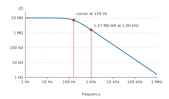
This is why an oscilloscope probe is specified on its capacitance rather than its resistance, and why the 10x probe exists at all.
Professional
Loading in the frequency domain and beyond
The lesson so far treats the circuit as resistive and the instrument as a resistance with a capacitor across it. Both simplifications give way in ordinary work.
A source with reactance in it has a source impedance rather than a source resistance, and the loading error becomes complex: the reading is wrong in phase as well as in size, and the size error varies with frequency even when the instrument's own input does not. On a resonant circuit the effect is dramatic, because an instrument across a tuned circuit lowers its Q factor and widens the very response the measurement was meant to characterise.
Instruments can also load a circuit without being connected to it. Capacitance between a probe lead and a nearby conductor is a path, and at high frequency it is a low-resistance one. This is why a probe lying across a board changes what the board does, and why a measurement that only works when you hold the lead a particular way is telling you something real.
The opposite problem exists too. A high-impedance node is not only easy to load, it is easy to disturb by injecting: mains hum, switching noise and static all couple into it through the same capacitance. Sometimes the honest answer is to redesign the measurement rather than the instrument, by measuring at a lower-impedance point and calculating back.
Where the source impedance is genuinely too high for anything, an active probe or a buffer amplifier moves the problem. A field-effect input can present many gigaohms and a fraction of a picofarad, at the cost of its own noise, its own bandwidth and a power supply. Electrometers take that further still, for measuring currents of a few picoamps where the instrument's own leakage becomes the limit.
The general form of all of this, stated once: Any measurement takes energy from what it measures, and the question is never whether it disturbs the system but whether it disturbs it by less than the precision you need. That is a design question, answered before the probes go on rather than after, and it belongs with the rest of accuracy, resolution and measurement error.
Common mistakes
- Reading a high-impedance node and believing the number. A divider of megohm arms read by a megohm meter is a different divider, and the reading is honest about the circuit that now exists.
- Assuming an analog meter's resistance is fixed. It is usually quoted as ohms per volt, so it changes with every range you select, and the low ranges load hardest.
- Using the same meter to check its own result. Two readings from one instrument agree with each other and prove nothing. Two instruments of different input resistance disagree in a way that tells you which is loading.
- Measuring a low resistance with two leads and calling the answer the part's. Everything in the current path is measured along with it, and below an ohm that is most of the reading.
- Treating the input resistance figure as the whole specification. Above a few hundred hertz the input capacitance dominates, and no datasheet puts that on the front panel.
- Adding a probe to a resonant or high-gain circuit and trusting what happens next. The instrument changed the Q, the bandwidth or the stability, and the trace is describing the new circuit.
Frequently asked questions
What is meter loading?
The change an instrument causes in the circuit it is measuring, by being another component in it. A voltmeter draws current and lowers the voltage it reads; an ammeter adds resistance and lowers the current it reads.
How much input resistance does a voltmeter need?
As a rule of thumb, a hundred times the source resistance for about one per cent error and a thousand times for a tenth of that. A 10 MΩ meter is therefore fine on anything up to about a hundred kilohms and questionable above a megohm.
Why does my analog meter read lower than my digital one?
Because its input resistance is far smaller, so it takes a much larger share of the current at the point being measured. On a 50 kΩ source, a 200 kΩ analog meter reads 20 % low where a 10 MΩ digital one reads 0.50 % low.
What is a four-wire or Kelvin measurement?
A connection that uses one pair of leads to carry the current and a separate pair to sense the voltage at the ends of the part itself. The sense pair carries almost no current, so lead and contact resistance drop out of the answer. It is how resistances below about an ohm are measured honestly.
Does input capacitance matter for DC measurements?
Not for the final reading, but it decides how long the reading takes to settle, because the source resistance has to charge it. On a gigaohm-range source with a hundred picofarads of input and lead capacitance, the time constant is a tenth of a second and the reading takes about half a second to settle, which is slow enough to notice. An ordinary megohm source settles the same capacitance in a tenth of a millisecond, far too fast to see.