
A bipolar transistor is two junctions sharing a terminal, so a meter's diode-test mode identifies it: the base is the only leg that reads forward to both others. The direction that reads forward gives the type, and collector-to-emitter should read open in both directions.
Intuition
Two junctions, and six ways to look at them
A bipolar transistor looks, to a meter, like two diodes sharing one terminal. That is not what it is — two diodes wired together do not amplify — but it is exactly what a diode-test probe sees, and it is enough to identify the device, work out its pinout, and tell a working one from a dead one.
Three legs means six ways to put two probes on them, and the pattern of what reads and what does not is a fingerprint. The base is the only leg that reads forward to both of the others. Find that leg and the rest follows: the direction it reads forward in gives the type, and the two remaining legs are the collector and the emitter.
What the test cannot do is anything quantitative. It says a junction is there; it does not say the device will do what its datasheet claims, and it does not say what will happen at the current your circuit will actually use.
And in four specific situations it will show you a perfectly reasonable number that means something else. Those four are worth more than the test itself, because a wrong reading you trust costs more than no reading at all.
Safety
A meter goes on circuits that may still hold charge. Power down, wait, and confirm with the meter itself that the supply rails and any large capacitors have actually discharged before probing — a circuit that is switched off is not necessarily a circuit that is safe to touch. Every reading quoted in this lesson is an illustrative figure chosen to make the arithmetic concrete: the test current, the compliance voltage, both junction voltages, the body diode's drop, the threshold and the gate capacitance. None is taken from any standard or any real instrument, and a real meter's own figures are on its own specification.
Practitioner
The test, and how to read it
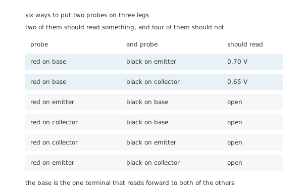
Two of them should read something, and four of them should not.
Set the meter to diode test, which pushes a small fixed current and shows the voltage that current produces. Then work through the six combinations.
Worked example — Identifying an unknown three-legged device
Find the base. Try the six pairs. One leg reads forward to both of the others — 0.70 V to one and 0.65 V to the other, at the meter's 1.0 mA of test current. That leg is the base.
Read the type from the direction. If the red probe was on the base for both forward readings, the base is the anode of both junctions and the device is an NPN. If the black probe was, it is a PNP.
Tell the collector from the emitter. The base-emitter junction reads slightly higher than the base-collector one — 0.70 V against 0.65 V — because the emitter is the more heavily doped side. It is a small difference and it is the least reliable step of the three; a pinout from the datasheet is better evidence.
Confirm with the pair that should not read. Collector to emitter must read open in both directions. Anything else is a failed device, and it is the most common failure there is.
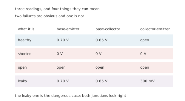
Two failures are obvious and one is not.
A shorted device reads near zero everywhere and an open one reads open everywhere; both are unmistakable. The third case is the one to watch: a leaky device whose two junctions read perfectly correctly, and which shows 300 mV collector-to-emitter where it should show open. It will often work well enough to look plausible in circuit and badly enough to be the fault you are chasing.
Engineer
What the reading does not say
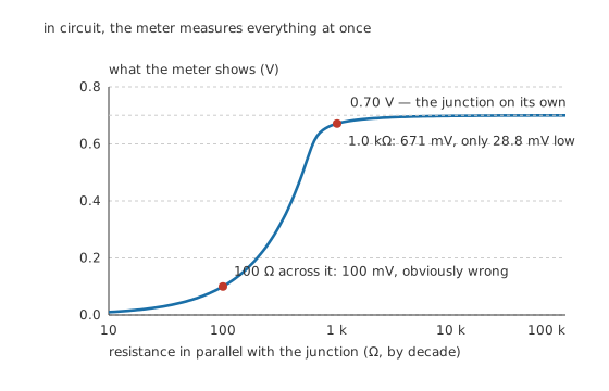
In circuit, the meter measures everything at once.
The first misleading case is the commonest, and it happens whenever the device is still soldered in.
Worked example — What a resistor across the junction does
The meter is a current source: it pushes 1.0 mA and reports the voltage that appears. If something else is connected across the junction, that current divides.
With 100 Ω across it — a base resistor, or a winding — the resistor alone takes the whole test current at a tenth of a volt, so the junction never gets far enough up its own curve to conduct at all. The meter shows 100 mV, which nobody would mistake for a junction.
With 1.0 kΩ across it, the split is finer. Solving the junction's exponential against the resistor for the voltage at which the two together take 1.0 mA gives 671 mV — only 28.8 mV below the unshunted 0.70 V.
That is the dangerous one. It is close enough to look right, and it is a reading of the resistor as much as of the transistor. Out of circuit, or with one leg lifted, is the only way to be sure what you measured.
The second misleading case is that the number is right for a current you will never use.
Worked example — The meter's current is not your circuit's
A junction's forward voltage rises with the logarithm of its current, by the thermal voltage per factor of e.
The meter tests at 1.0 mA. A circuit running the same junction at 100 mA — a hundred times more — puts it 119 mV higher, at 819 mV.
So the 0.70 V on the screen is a true reading of a condition your circuit will never be in. For identifying a device that is fine; for calculating a bias point it is not.
The third is a device that has more junctions than you expect. A Darlington reads 1.40 V base to emitter, because two junctions are in the path, and a meter whose compliance stops short of that will report the device as open when it is perfectly good.
Professional
MOSFETs, which have to be turned on to be tested
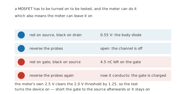
A MOSFET has to be turned on to be tested, and the meter can do it.
A MOSFET has no junction from gate to anything, so the diode test finds nothing there — an open reading in both directions, which is the correct result and looks like a dead device.
Worked example — The four-step sequence
One. Red on the source, black on the drain. This reads the body diode forward, at 0.55 V, because the body is tied to the source and the drain is its cathode.
Two. Reverse the probes. Open — the channel is off and the body diode is now reverse-biased.
Three. Touch red to the gate and black to the source. Nothing to read, but something has happened: the meter's 2.5 V has charged the gate, leaving 4.5 nC on it. That clears the device's 2.0 V threshold by 1.25, so the channel is now on.
Four. Repeat step two. It now reads low in both directions, because the channel is conducting.
And it stays that way, because nothing discharges an insulated gate. Short the gate to the source with a probe or a finger to turn it off again — and remember that the same mechanism is what makes an undriven gate a hazard in a real circuit rather than a curiosity on a bench.
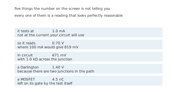
Every one of them is a reading that looks perfectly reasonable.
What the test is good for, and what it is not
Good for: identifying an unknown device's base and type; distinguishing a bipolar from a MOSFET; confirming a suspected short or open; sorting a bag of unmarked parts into families. All of that is quick, reliable, and needs nothing but the meter.
Not good for: anything about gain. A meter's hFE socket runs the device at a current of its own choosing, and the gain a transistor shows there is not the gain it will have in your circuit at your current — a relation the gain lesson treats properly. Nor does the test say anything about breakdown voltage, speed, or capacitance, all of which are how a device more usually disappoints.
And not good for: a device still in circuit, unless the reading happens to be one of the unambiguous ones. A junction reading 671 mV instead of 0.70 V is a reading of the circuit, not of the transistor.
The habit worth forming
Test the same pin pair on a known-good device before you conclude anything about a suspect one. Every number in this lesson depends on a meter's own test current and compliance, and those vary between instruments — so the reliable comparison is not against a number you remember but against the same measurement on a part you trust.
Common mistakes
- Testing in circuit and believing the number — 1.0 kΩ across a junction turns a 0.70 V reading into 671 mV, which is only 28.8 mV low and looks entirely normal.
- Using the reading as a bias figure — the meter tests at 1.0 mA; the same junction at 100 mA sits 119 mV higher, at 819 mV.
- Declaring a Darlington dead — it reads 1.40 V base to emitter because two junctions are in the path, and a meter that cannot reach that shows it as open.
- Expecting a gate-to-source junction on a MOSFET — there is none, and the open reading is the correct one. Test the body diode instead.
- Leaving a MOSFET's gate charged — the meter's own 2.5 V leaves 4.5 nC on it, enough to hold the device on afterwards. Short gate to source before putting it down.
- Trusting the hFE socket — it measures gain at its own test current, which is not the current your circuit will use.
Parts used in this topic
Frequently asked questions
How do I find the base of an unknown transistor?
It is the only leg that reads forward to both of the others — 0.70 V to one and 0.65 V to the other at the meter's 1.0 mA. If the red probe was on that leg for both readings the device is an NPN; if the black probe was, it is a PNP.
Can I tell the collector from the emitter with a meter?
Usually, and not reliably. The base-emitter junction reads slightly higher than the base-collector one — 0.70 V against 0.65 V here — because the emitter is more heavily doped. It is a real difference and a small one, so a datasheet pinout is better evidence.
Why does an in-circuit reading come out low?
Because the meter's test current divides between the junction and whatever else is connected across it. With 1.0 kΩ in parallel the reading falls to 671 mV, only 28.8 mV low. With 100 Ω it falls to 100 mV, which is obviously not a junction at all.
Why does a MOSFET read open everywhere?
Because its gate is insulated, so there is no junction to find there. Test the body diode instead: red on the source and black on the drain reads about 0.55 V, and the reverse reads open until the gate has been charged.
Can the meter itself turn a MOSFET on?
Yes, and that is how the test works. Touching the red probe to the gate leaves 4.5 nC on it at the meter's 2.5 V, which clears a 2.0 V threshold by 1.25 — so the channel conducts and stays conducting until the gate is shorted to the source.
Knowledge check
How do you identify an unknown bipolar transistor with a meter? (Show answer)
What are the four signatures on the three probe pairs? (Show answer)
Why is an in-circuit reading unreliable? (Show answer)
Why is the reading not the junction voltage your circuit will see? (Show answer)
Walk through testing a MOSFET. (Show answer)
One email a month from the bench
New circuits, lessons, part guides and calculators, on the first Sunday of each month.