

Quick Answer
Voltage is the amount of energy carried per unit of electric charge between two points in a circuit. Its SI unit is the volt, and one volt means one joule of energy per coulomb of charge. Because it is a difference, a voltage figure only has meaning once the second point is known.
Intuition
The push behind the flow
If current is how much electricity flows, voltage is the push that makes it flow. A circuit sits inert until something establishes a voltage across it.
The water picture is the useful one again. Imagine two tanks joined by a pipe, one raised above the other. Water flows because of the height difference, not because of the height. Raise both tanks by the same amount and nothing changes. Voltage works the same way: it is a difference between two points, which is why the proper name for it is potential difference.
There is no such thing as the voltage at a point, and that catches out almost everyone at the start. When someone says "this pin is at 5 V" they mean 5 V relative to a point in the circuit that everyone has agreed to call zero — the ground. Change the reference and the number changes, while the circuit behaves identically.
A battery is a device that maintains such a difference. An AA cell holds 1.5 V between its terminals; a USB port holds 5 V; a wall socket in India holds a couple of hundred, alternating rather than steady. Each of those numbers describes how hard the source pushes, not how much current flows — that depends on what you connect.
A voltmeter has two leads for the same reason: it has to sample two points before it has anything to report. Every voltage you quote, measure or design around is a number attached to a pair of points, even when only one of the pair ever gets named.
Practitioner
Volts, joules and coulombs
The volt is defined by what it does to charge. Move a charge from one point to another and the energy it gains or loses, divided by the charge, is the voltage between those points:
One volt is one joule per coulomb. That definition ties electrical quantities directly to energy, and it is why voltage multiplied by current gives power.
Worked example — Voltage from energy and charge
A source delivers 27 J of energy while moving 3 C of charge round a circuit.
Dividing the energy by the charge gives the potential difference the source is maintaining: 9.0 V. Neither time nor resistance appears anywhere in that division. Voltage is a property of the source and the circuit's arrangement, not of how fast the charge happens to be moving.
A voltmeter goes across the component of interest, in parallel, with the circuit left intact. It is built with a very high input resistance — tens of megohms for a decent multimeter — precisely so that connecting it changes almost nothing. A current measurement works the other way round, since the circuit has to be broken and the meter inserted into the path.
Rails you meet constantly: 1.8 V, 3.3 V and 5 V for logic; 12 V and 24 V for motors, relays and industrial gear; 230 V mains in India and much of the world, 120 V in North America. Japan follows neither convention — its domestic supply is 100 V, and the grid frequency differs between the east and the west of the country. Logic families care about voltage more than anything else, because their input thresholds are defined in volts — see logic levels.
Voltages in series add. Two cells connected positive-to-negative give the sum of their individual voltages, which is how battery packs are built — see batteries in series and parallel. Connect one of them backwards and it subtracts instead, which is the usual explanation for a pack that reads far too low.
Every reading also needs a reference. Circuits nominate one node as zero volts, mark it as ground, and quote every other node relative to it. That choice is a convention rather than a physical fact, but it has to be applied consistently, and where two systems each nominate their own it becomes a real design problem. Ground and reference points covers it.
One thing voltage does not tell you is how much energy is available. A charged capacitor and a car battery can sit at the same voltage and differ by a factor of millions in stored energy, because energy depends on the charge behind the voltage as well as on the voltage itself. See electrical energy.
Engineer
Potential, EMF, and why the number moves when you load it
Formally, the electric potential at a point is the work per unit charge needed to bring a test charge there from a chosen reference. Potential difference between two points is the quantity we actually measure, and it is path-independent: move a charge from one node to another by any route and the energy exchange is the same. That path-independence is exactly what makes Kirchhoff's voltage law true — go round any closed loop and the potential differences must sum to zero, because you have arrived back where you started.
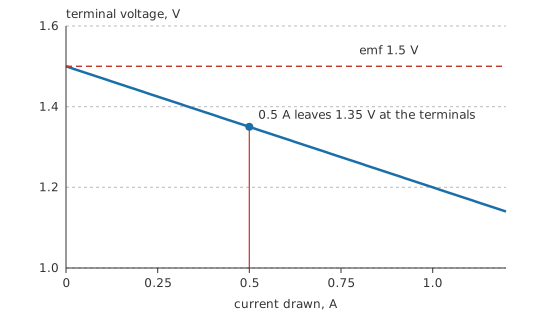
A source's electromotive force (EMF) is the potential difference it would maintain with nothing drawing current. Its terminal voltage is what you actually measure with a load connected, and the two are never equal, because every real source has internal resistance. Current through that internal resistance produces a drop inside the source, and the load sees what is left.
Worked example — Why a cell reads lower under load
A cell has an open-circuit EMF of 1.5 V and an internal resistance of 0.3 Ω. A load draws 0.5 A from it.
Multiplying that current by the internal resistance gives the drop that happens inside the cell: 0.15 V. Subtracting it from the EMF leaves the terminal voltage the load actually sees: 1.35 V.
A healthy cell behaves exactly like this, and the missing volts are ordinary and expected. It is the reason an open-circuit measurement makes such a poor battery test — a nearly dead cell can read close to its nominal EMF and collapse the moment current is drawn — and the reason battery testers measure internal resistance rather than voltage.
Measuring a voltage always disturbs it a little. A voltmeter's finite input resistance sits in parallel with whatever it measures, forming a divider with the source impedance. Across a low-impedance node the error is negligible; across a megohm-scale node an ordinary meter can read substantially low, and a ten-megohm meter across a ten-megohm source reads half the true value. The same effect at high frequency is why oscilloscope probes attenuate: a 10× probe trades signal amplitude for a tenfold reduction in loading.
Ask for the voltage of an AC waveform and the answer needs a qualifier. Peak, peak-to-peak, average and RMS are four different numbers for the same waveform, and only the RMS value produces the same heating as an equal DC voltage. Mains quoted as 230 V is an RMS figure; its peak is substantially higher, which is what the insulation and the rectifier actually have to withstand. See RMS value and DC vs AC.
Some voltages have no relationship to your ground at all. A measurement between two nodes that are both well away from ground is a differential measurement, and taking it with a ground-referenced instrument either shorts something out or reads the wrong thing. Differential probes, isolated inputs and instrumentation amplifiers exist for this, and the associated specification — how much common-mode voltage the input can tolerate while still reporting the difference correctly — is usually the one that decides whether an instrument is usable.
Professional
Rails, tolerances and the volts that go missing
A rail is a specification rather than a number. A "3.3 V" supply is really a window: the nominal value plus a tolerance, plus regulation error as the load changes, plus ripple, plus whatever the distribution network takes out of it. Digital logic tolerates a surprising amount of this and analogue circuitry does not, which is why precision references, ADCs and RF blocks so often get their own regulator rather than sharing.
Every conductor has resistance, so every conductor carrying current develops a voltage across it — and that voltage subtracts from the supply the load receives, or adds to the ground the load thinks is zero. IR drop is the most under-estimated error on a board.
A return path of 50 mΩ carrying 2 A develops 100 mV across itself. On a low-voltage core rail that is a substantial fraction of the entire tolerance budget, and it is spent before the load has done anything useful. Worse, it appears as a ground shift, so any signal referenced to the far end of that path is offset by the same amount. This is what wire resistance and voltage drop is about, and it is why power distribution has to be settled on the layout rather than on the schematic.
Remote sensing. Separate, current-free sense wires run from the regulator's feedback to the actual load, so the regulator compensates for the distribution drop instead of ignoring it. The same idea appears as four-terminal Kelvin connection on current-sense resistors and on precision measurement fixtures. The rule is the same in both: never take a voltage measurement through a conductor that is carrying the current.
An absolute-maximum voltage marks the point beyond which damage may occur, and says nothing about the part working there. Design to the recommended operating conditions, and remember that inductive kick, hot-plug transients, ESD and supply sequencing can all take a pin outside the rails momentarily. Treat input protection and clamping as part of the design rather than as a rescue for a bad one.
Isolation and spacing. Where two circuits must not share a reference — mains-connected equipment, medical devices, high-side gate drive, industrial buses — the separation is enforced physically, and IEC 60664 specifies creepage and clearance distances from working voltage, pollution degree and material group. These distances set board geometry, so they belong in the design before layout starts, not after.
Safety
Mains voltages and stored energy both kill. Treat any circuit connected to the mains as live until proven otherwise, use test equipment with an appropriate CAT rating and rated leads, and never bridge an isolation barrier with a ground-referenced instrument — use a differential or isolated probe.
Voltage does not disappear when the power is switched off. Bulk capacitors in power supplies, camera flash circuits and motor drives can hold a lethal charge for a long time after disconnection; discharge them deliberately through a suitable resistor and verify with a meter before touching anything. The practices in Electrical Safety Fundamentals apply to every one of these cases.
Common mistakes
- Talking about the voltage at a point — voltage is always between two points. "At a point" always means "relative to ground", and the reference must be stated when it is not obvious.
- Testing a battery open-circuit — a nearly exhausted cell reads close to its nominal voltage until current is drawn. Test under a realistic load, or measure internal resistance.
- Measuring a high-impedance node with an ordinary meter — the meter's input resistance loads the node and the reading comes out low. Check the source impedance against the meter's before believing the number.
- Quoting an AC voltage without saying which one — peak, peak-to-peak and RMS differ substantially, and only RMS is comparable to a DC voltage for heating.
- Ignoring the drop in the ground return — it shifts the reference for everything downstream of it, turning a power problem into a signal-integrity problem.
- Designing to absolute maximum ratings — those are damage thresholds, not operating conditions.
Frequently asked questions
What is voltage in simple terms?
It is the electrical push between two points — the energy each unit of charge carries from one point to the other. One volt is one joule per coulomb.
Why is voltage always measured between two points?
Because it is a difference. Potential on its own depends on an arbitrary reference; only the difference between two points has physical consequences, and only the difference drives current.
What is the difference between EMF and terminal voltage?
EMF is what a source maintains with no current drawn. Terminal voltage is what it delivers under load, which is lower by the drop across its own internal resistance.
Does a higher voltage always mean more energy?
No. Energy depends on charge as well as voltage. A small capacitor and a car battery at the same voltage hold wildly different amounts of energy.
Why does my supply read correctly at the regulator but low at the load?
Because the conductors between them have resistance, and current through resistance produces a voltage drop. Remote sensing, thicker copper or a shorter path are the fixes.
Is it voltage or current that is dangerous?
Current through the body does the damage, but voltage is what drives it — which is why safety limits are written in volts. High voltage across a person's resistance is what produces a dangerous current.
Knowledge check
A source delivers 27 J of energy while moving 3 C of charge. What is its voltage? (Show answer)
Can you measure the voltage at a single point in a circuit? (Show answer)
Two identical cells of 1.5 V are connected in series, positive to negative. What is the voltage across the pair? (Show answer)
A cell measures 1.5 V with nothing connected but 1.35 V under load. Where did the difference go? (Show answer)
Why is a voltmeter connected in parallel while an ammeter is connected in series? (Show answer)
References
- Bureau International des Poids et Mesures, The International System of Units (SI), 9th edition — the volt as a coherent derived unit, one joule per coulomb.
- IEC 60664-1, Insulation coordination for equipment within low-voltage supply systems — creepage and clearance distances as a function of working voltage, pollution degree and material group.