
Quick Answer
A first-order circuit contains a single effective capacitance or inductance, and every such circuit settles along the same exponential after a switch operates. Three numbers describe it completely: the value at the instant of switching, the value it is heading for, and the time constant that sets how fast it gets there.
Intuition
Everything settles the same way
Put a hot mug down on a desk and it cools quickly at first, then more slowly, and it approaches room temperature without ever quite reaching it. Nobody solves a differential equation to predict that. Knowing how hot it started, how cold the room is, and roughly how long the mug takes to lose interest is enough to sketch the whole curve.
Circuits with one energy store behave in exactly the same way, and for exactly the same reason: in each case the rate of change is proportional to how far the thing still has to go. A capacitor charging through a resistor, an inductor building current, a mug cooling, a tank draining — all of them are described by the same equation with different letters, and all of them produce the same exponential shape.
That is what makes this material worth learning once rather than case by case. The RC and RL lessons each dealt with one particular arrangement. This lesson takes the general version, which handles any single-storage-element circuit regardless of what is around it, and regardless of whether the quantity of interest is rising, falling, or heading somewhere that is neither zero nor the supply.
Three numbers do it. Where the quantity starts, where it is going, and how quickly. Everything else in this lesson is about how to find those three.
Practitioner
The recipe
For any first-order circuit, the quantity of interest at time t after the switch operates is:
Read it as a starting value that decays away and a final value that takes over. At t = 0 the exponential is 1 and the whole expression collapses to the initial value. As t grows the exponential vanishes and only the final value is left. In between, the gap between them closes by the same fraction in each time constant.
The method for using it is always the same three steps:
- Find the value at the instant of switching. A capacitor's voltage and an inductor's current cannot change instantly, so whatever either of them held just before the switch operated is what it holds just after. Work out the circuit's steady state before the switch and read that one quantity off it.
- Find the value it settles at. Let the circuit run until nothing is changing, then treat every capacitor as an open circuit and every inductor as a plain wire, and solve the resulting DC circuit.
- Find the time constant. Turn off the independent sources — voltage sources become shorts, current sources become opens — and find the resistance the storage element sees looking back into the rest of the circuit. That resistance with the capacitance gives RC, or with the inductance gives L over R.
Worked example — A capacitor that starts high and settles low
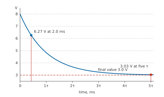
A capacitor of 1.0 µF sits at 8.0 V when a switch connects it, through 4.7 kΩ, to a rail at 3.0 V.
Step three first, since it is independent of the voltages: the time constant is 4.7 ms.
At 2.0 ms after switching, the capacitor is at 6.27 V, on its way down.
After five time constants it has reached 3.03 V, which is its final value for any practical purpose.
The plain charging law is this expression with an initial value of zero, and the plain discharging law is it with a final value of zero. Neither can express the case above, where the quantity travels between two non-zero values, and that case is the common one in real circuits — which is why this form is the one worth remembering.
Engineer
Where the three numbers come from when the circuit is not trivial
Step three is the one that does real work, because the resistance the storage element sees is rarely the resistor drawn next to it. Finding it is a Thévenin calculation with the storage element removed, and the same calculation usually hands you step two as a by-product.
Worked example — The recipe on a divider with a capacitor across the lower leg
A source of 15 V feeds 4.7 kΩ into a node, with 10 kΩ from that node to ground and 220 nF across it. The capacitor starts at 0.0 V, and the switch closes at time zero.
Final value. With the capacitor treated as an open circuit, the node is a plain divider: 10.2 V.
Time constant. Shorting the source puts both resistors in parallel as seen from the capacitor, giving 3.20 kΩ, and with the capacitance that is 703 µs.
The answer. At 1.0 ms the node sits at 7.74 V.
Taking 4.7 kΩ alone would have predicted a time constant half as long again, and the answer at that instant would have been wrong by most of a volt. The resistance that matters is the one the capacitor sees, not the one it is wired to.
Nothing in that method mentioned capacitors specifically, which is the point of doing it this way:
Worked example — The same network, with an inductor instead
Replace the capacitor with 10 mH. Steps one and two are unchanged, and step three uses the same 3.20 kΩ — but divided into the inductance rather than multiplied by the capacitance, giving 3.13 µs.
Only the arithmetic of the third step differs. The recipe, and the exponential it feeds, are identical.
Where the equation comes from is worth one paragraph. Apply KVL round the loop with the storage element's own relation substituted in, and the result is a first-order linear differential equation: something proportional to the rate of change, plus something proportional to the quantity itself, equals a constant. Its solution is always a constant part — the final value, which is what remains when the rate of change is zero — plus a decaying exponential whose amplitude is fixed by the initial condition. The expression in Layer 2 is that solution with the two constants named after the things you can actually measure.
The method's conditions are worth stating plainly, because it is easy to apply it where it does not hold. The circuit must be linear, so it needs constant resistances and a capacitance or inductance that does not depend on the voltage or current across it. It must have exactly one effective storage element, which is not the same as one component — several capacitors that combine into a single equivalent still count as one. And the sources must be constant over the interval being analysed; a source that is itself changing needs the more general convolution treatment rather than this shortcut.
Professional
Using it on circuits that only look complicated
Plenty of circuits with several capacitors are still first-order, and recognising them saves a great deal of work.
Capacitors in parallel with each other combine into one; so do capacitors in series with each other, provided nothing connects to the node between them. What makes a circuit genuinely second-order is two storage elements that cannot be combined — typically one capacitor and one inductor, or two capacitors separated by a resistor. If the storage elements collapse to a single equivalent under the series and parallel rules, the method above still applies unchanged.
Switched circuits usually have a different time constant in each phase, and the difference is often the design intent rather than an accident.
Worked example — Charging fast and discharging slowly
Take the network from Layer 3 and give it a second phase in which the capacitor discharges through 100 kΩ instead.
That phase has a time constant of 22 ms, against 703 µs for the charging phase — a ratio of 31.3.
The same capacitor, two quite different speeds, chosen by which resistance is in circuit. Peak detectors, envelope followers and the asymmetric duty cycles of timer circuits are all built on exactly this.
The initial-condition step is where mistakes concentrate, and the rule is narrow. It is a capacitor's voltage and an inductor's current that cannot jump, because jumping would require infinite current or infinite voltage respectively. Everything else in the circuit is free to change instantly, and usually does. A capacitor's current, an inductor's voltage, and every resistor's current can all step discontinuously at the moment of switching, and the instant just after the switch is often where the largest values in the whole problem appear.
Analysing a sequence of switching events means carrying the state forward: the value at the end of one interval becomes the initial value for the next. A circuit switched repeatedly does not settle to the same starting point each cycle unless it has had five time constants to do so, and a periodic circuit switched faster than that eventually reaches a periodic steady state in which each cycle's start and end match — which is the normal operating condition of every switching converter, and never the fully-settled DC state a first analysis assumes.
Simulation is the usual tool for anything beyond a few intervals, and the value of the hand method is not that it competes. It is that it tells you what the simulator's answer should look like. Knowing the three numbers before running the analysis means an implausible result gets caught, which is exactly the discipline circuit simulation recommends.
Where the model runs out, it does so predictably. A capacitance that changes with voltage makes the response non-exponential. A core that saturates does the same. Long time constants meet leakage and bias currents that the ideal model ignores, and above a few megahertz the parasitics that the lumped model leaves out have their own transients. All of those show up as a measured curve that starts on the predicted trajectory and then departs from it, which is a more useful diagnostic than a curve that was wrong from the start.
Common mistakes
- Using the plain charging law where the quantity starts somewhere other than zero — the general form handles any pair of initial and final values, and most real cases have both non-zero.
- Taking the time constant from the resistor next to the capacitor — it is the resistance the storage element sees with the sources deactivated, which is usually a parallel combination.
- Assuming a capacitor's current is continuous — it is the voltage that cannot jump. The current at the instant after switching is often the largest in the problem.
- Treating any circuit with two capacitors as second-order — if they combine into one equivalent, the circuit is still first-order and the same method applies.
- Forgetting that each switching phase has its own time constant — charge and discharge paths usually differ, and the asymmetry is often deliberate.
- Expecting a repeatedly switched circuit to start from rest each cycle — after a few cycles it settles into a periodic state that begins wherever the previous cycle left off.
Frequently asked questions
What makes a circuit first-order?
Having a single effective energy-storage element — one capacitance or one inductance, after any that combine have been reduced. Its response to a step is always a single exponential.
What are the three numbers I need?
The value at the instant of switching, the value the circuit settles at, and the time constant. With those three, the response at any time follows directly from the general expression.
How do I find the time constant of a circuit with several resistors?
Deactivate the independent sources — short the voltage sources, open the current sources — and find the resistance seen from the terminals of the storage element. That resistance is the one that goes into RC or L over R.
Which quantities cannot change instantly at a switching instant?
A capacitor's voltage and an inductor's current, because changing either instantly would need infinite current or infinite voltage. Everything else in the circuit can and often does step.
Does the method work for inductors as well as capacitors?
Yes, unchanged apart from the time-constant step. The initial and final values and the exponential are identical; only RC becomes L over R.