
Quick Answer
A second-order circuit holds energy in two places that cannot be combined, typically an inductance and a capacitance, so energy can slosh between them. Two numbers describe it: a natural frequency setting how fast it wants to oscillate, and a damping ratio deciding whether it rings, creeps, or settles cleanly.
Intuition
The door closer
A door with a hydraulic closer fitted can behave in three quite different ways, and everyone has met all three. Adjusted too freely, the door swings past the frame and slams. Adjusted too tightly, it drifts shut so slowly that you give up waiting. Adjusted correctly, it arrives at the frame quickly and stops there without a bang.
The mechanism is the same in all three cases: a spring that wants to close the door, a mass that wants to keep moving, and a damper that resists motion. Only the damper's setting changes. Too little damping and the mass overshoots; too much and it never gets going; the right amount and the door lands.
A circuit with two energy stores does exactly the same thing, and for the same reason. A capacitor stores energy in a voltage and an inductor stores it in a current, so when both are present the energy can transfer from one to the other and back — which is oscillation. Resistance plays the damper's part, taking energy out of the exchange every time round.
That gives the three regimes this lesson is about. Underdamped: the response overshoots and rings before settling. Overdamped: it creeps to its final value without ever passing it. Critically damped: it arrives as quickly as possible without overshooting, the door-closer setting everyone wants and nobody quite achieves.
Everything a first-order circuit does is contained in the middle of that list. With only one energy store there is nowhere for the energy to slosh to, so ringing is not available and every response is a plain exponential.
Practitioner
The two numbers that describe it
A second-order circuit is characterised by a natural frequency and a damping ratio, and everything else follows from those two.
The natural frequency is the rate at which the two stores would exchange energy if there were no resistance at all:
The damping ratio says how heavily that exchange is being drained. For a series RLC arrangement:
A damping ratio below one is underdamped and rings; above one is overdamped and creeps; exactly one is critical.
Worked example — A series RLC, and which regime it is in
Take 10 µH and 100 nF in series with 5.0 Ω.
The natural angular frequency is 1.0 Mrad/s, which as an ordinary frequency is 159 kHz.
The damping ratio comes out at 0.25, comfortably below one — so this circuit rings.
It rings slightly below its natural frequency, at 968 krad/s, because damping slows the exchange a little.
And it overshoots its final value by 44.4 % on the first peak, which is a great deal for a supply rail or a logic input to put up with.
Raising the resistance to 20 Ω would bring the damping ratio to exactly one and stop the ringing altogether.
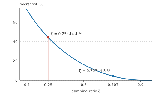
The ringing frequency and the overshoot are both worth having as separate numbers:
The overshoot depends on the damping ratio and on nothing else — not on the component values, not on the step size, not on the frequency. That makes it a direct measurement: read the overshoot off a scope trace and the damping ratio follows, without knowing any of the components.
A word of warning about the damping-ratio expression. It is written for the series arrangement, where the resistance is in the path the current takes. In a parallel RLC the resistance sits across the pair instead, and its effect reverses: more resistance means less damping. Reading the series formula onto a parallel circuit gives the wrong answer with confidence, so the first job is always to identify which arrangement is in front of you.
Engineer
Where the regimes come from
Apply KVL round a series loop containing a resistance, an inductance and a capacitance, and substitute each element's own relation. What comes out is a second-order differential equation: a term in the second rate of change of the charge, a term in the first, and a term in the charge itself.
The solution's character is decided by the roots of the equation's characteristic polynomial, and a quadratic has three possibilities. Two complex roots give a decaying sinusoid, which is ringing. Two distinct real roots give a sum of two decaying exponentials, which is a creep. A repeated real root gives the boundary case. Which of the three occurs depends entirely on the sign of the discriminant, and rewriting that condition in terms of the components is exactly what produces the damping ratio: the discriminant changes sign at ζ = 1.
Worked example — The same L and C, heavily damped
Keep 10 µH and 100 nF and raise the series resistance to 100 Ω.
The damping ratio becomes 5.0, well above one, so the response is overdamped: two real exponentials, no ringing, and a settling time considerably longer than the critically damped case would give.
That is the trade in one line. Adding resistance removes the overshoot and slows everything down, and past the critical point there is nothing left to gain.
Damping is often quoted the other way up, as a quality factor. Q is one over twice the damping ratio, so a lightly damped circuit has a high Q and a heavily damped one a low Q:
Worked example — The same circuit, in the other currency
The 0.25 damping ratio of the Layer 2 circuit corresponds to a Q of 2.0.
Both numbers say the same thing. Damping ratio is the natural language for a step response and Q for a resonant one, and a design specified in one is often analysed in the other.
Where does the energy go while all this is happening? In the undamped case it shuttles endlessly between the capacitor's electric field and the inductor's magnetic field, with the total constant — the capacitor is fully charged at the moments the current is zero, and the inductor carries peak current at the moments the capacitor is empty. Resistance takes a bite out of the total on every pass, which is why the ringing decays. The decay envelope's own time constant is set by how big that bite is, and it is what the damping ratio measures.
The model's conditions are the usual linear ones, and they matter here more than usual. Constant L and C are assumed, so a saturating core or a bias-dependent ceramic makes the ringing frequency move during the transient itself. Exactly two independent energy stores are assumed, so a circuit with three produces a third-order response that this treatment does not describe. And a step input is assumed; a slower input excites the resonance less, which is the mechanism behind slowing an edge to stop a circuit ringing.
Professional
Placing the damping where you want it
Most second-order behaviour in real circuits is unintentional. Nobody fits the inductance; it arrives as lead inductance, track inductance or a transformer's leakage, and it finds a capacitance to resonate with.
The signature is unmistakable once recognised: a fast edge followed by a decaying oscillation, at a frequency far above anything the circuit is meant to produce. Switching-node waveforms, relay contacts, cable-driven signals and the supply rail beside a fast driver all show it. The frequency identifies the culprits, since it is the natural frequency of whatever inductance and capacitance are involved, and a rough measurement of it narrows the search considerably.
Fixing it means adding damping, and there are only a few places to put it. A resistor in series with the offending loop raises the damping ratio directly, at the cost of a voltage drop wherever current flows. An RC snubber across the ringing element adds damping only at the ringing frequency, which is why it is preferred where a plain series resistor would be too lossy. A ferrite bead is a frequency-selective resistance that does much the same job. And slowing the driving edge reduces the excitation rather than the resonance, which is often the cheapest fix of all.
Where damping is chosen deliberately, the usual target is a damping ratio around 0.7 rather than 1:
Worked example — Why designs aim just short of critical
At a damping ratio of 0.707, the overshoot is 4.3 %.
That is small enough to be harmless in most circuits, and the response reaches its final value faster than a critically damped one does. Insisting on zero overshoot costs settling time, so a few per cent is usually the better bargain.
Component tolerance moves the damping ratio around, and the movement is not symmetric in its consequences. The ratio depends on the square root of C over L, so a twenty per cent capacitor and a twenty per cent inductor together move it by around ten per cent — modest. What is not modest is the effect near the boundary: a design placed at exactly critical damping will be underdamped in half the units built, so the target is chosen with margin on whichever side matters.
A second-order response can be unstable rather than merely underdamped, if something in the circuit supplies energy in phase with the oscillation instead of removing it. A control loop with too much phase lag does this, and so does a switching regulator whose compensation is wrong; the symptom is ringing that does not decay, or grows. And a resonance with almost no damping is not always a fault — it is exactly what a crystal or an LC oscillator is built to be, where the goal is the highest Q obtainable rather than a clean step response.
The measurement route is worth remembering because it needs no component values at all. Capture the step response, count the overshoot to get the damping ratio, and read the ringing period to get the damped frequency; those two together give the natural frequency, and from there the effective L and C follow. It is the standard way to characterise a parasitic resonance whose components nobody drew.
Common mistakes
- Using the series damping-ratio expression on a parallel RLC — the effect of resistance reverses between the two, so the answer is not merely inaccurate but backwards.
- Aiming for exactly critical damping — component tolerance puts half the production run on the underdamped side. Aim short of it deliberately.
- Treating ringing as a component fault — it is almost always parasitic inductance finding a capacitance, and the ringing frequency identifies which ones.
- Adding series resistance to damp a supply rail — it damps the ringing and drops voltage at every ampere. A snubber or a bead damps at the ringing frequency without the DC penalty.
- Assuming overshoot depends on the step size — it depends on the damping ratio alone, which is what makes it measurable straight off a trace.
- Calling any circuit with two capacitors second-order — if they combine into one equivalent, the circuit is still first-order and cannot ring.
Frequently asked questions
What makes a circuit second-order?
Two independent energy stores that cannot be combined into one — usually an inductance and a capacitance. Energy can then transfer between them, which is what makes oscillation possible.
What does the damping ratio tell me?
Which of the three regimes the circuit is in. Below one it rings, above one it creeps to its final value without overshooting, and exactly one is the fastest response with no overshoot at all.
How do I measure the damping ratio without knowing the components?
Read the overshoot on the first peak of the step response. Overshoot depends only on the damping ratio, so the trace gives it directly, and the ringing period then gives the frequency.
Why do designs aim for a damping ratio near 0.7 rather than 1?
Because it settles faster while overshooting by only a few per cent. Insisting on zero overshoot costs settling time, and component tolerance would put many units on the ringing side of critical anyway.
My switching node rings at a frequency nothing in the circuit produces. Why?
Parasitic inductance — leads, tracks, transformer leakage — resonating with a capacitance that is also mostly parasitic. The ringing frequency is that pair's natural frequency, and it points at which parts are involved.