
Quick Answer
Phase is the position a repeating wave has reached within its cycle, stated as an angle out of 360 degrees. Phase difference is the constant angle between two waves of the same frequency, and it corresponds to a fixed delay between them: a quarter of a cycle is 90 degrees.
Intuition
Two metronomes started a moment apart
Two metronomes set to the same speed, with the second started a moment after the first, tick along together for as long as they run, and the gap between their ticks never grows or shrinks. Neither is faster than the other. What separates them is where each one happens to be in its swing at any given instant, and that separation was decided once, by how late the second one was started.
Phase is the same idea applied to a repeating electrical signal. A sine wave goes through the same sequence every cycle: up through zero, over the top, back down through zero, under the bottom, and round to the start again. Phase names the point reached in that sequence, and it is quoted as an angle, since one whole cycle is one whole turn of 360 degrees. A quarter of the way through is 90 degrees, halfway is 180.
A single wave on its own has no phase worth reporting. The clock has to start somewhere, and where it starts is a free choice. The useful quantity is phase difference, the separation between two waves running at the same frequency. One of them will generally reach each landmark before the other. The one in front leads, the one behind lags, and the angle between them stays put.
That angle is the reason alternating current takes more arithmetic than direct current. A capacitor or an inductor does not simply make a voltage larger or smaller. It moves the current in time relative to the voltage, and how far it moves decides how much of the electricity going in is doing any work.
Practitioner
Turning a delay into degrees
A phase difference is measured as a time and reported as an angle. Put both signals on an oscilloscope, choose a landmark that appears on both traces, and read the horizontal distance between them. The upward zero crossing is the usual landmark: it is the steepest part of a sine wave, so noise moves it least. A peak makes a poor landmark for the mirror-image reason, since the trace is flat there and a small disturbance shifts the apparent instant a long way.
A distance in microseconds means nothing until it is set against the length of one cycle, so the period has to be known too:
The delay divided by the period is the fraction of a cycle separating the two waves, and 360 of those fractions make a full turn:
Worked example — A quarter-cycle separation at one kilohertz
Both traces run at 1.0 kHz, so one cycle occupies 1.0 ms.
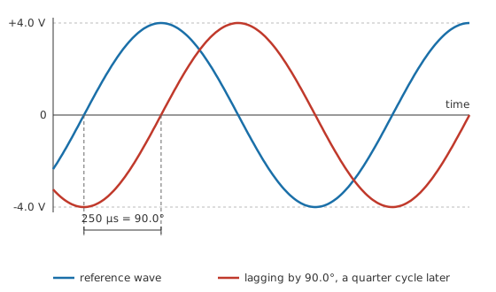
The cursors land 250 µs apart, a quarter of that period, and the phase difference is 90.0°.
Ninety degrees is worth learning to spot without measuring anything: one trace passes through zero at the instant the other reaches its peak. An ideal capacitor and an ideal inductor each put that much separation between their voltage and their current, in opposite directions, and the opposing signs on capacitive reactance and inductive reactance come from that difference in direction.
Most real circuits produce something smaller and less tidy, and those are the readings that need the arithmetic done properly.
Worked example — A smaller separation on the same pair
The two waves are brought closer together, to 83.3 µs of separation, with the period unchanged at 1.0 ms.
The phase difference comes to 30.0°. Either description works as a sanity check on the other: a third of the earlier delay, and a third of the earlier angle.
Which wave leads and which lags is not something a still picture can settle on its own. A lag of a quarter cycle puts the traces in the same place a lead of three quarters would, and a scope screen shows no difference between the two. Convention resolves it by taking the smaller angle, so anything past 180 degrees of lag is reported as a lead instead, and by naming the reference wave explicitly. On the bench the honest method is to change something and watch which trace responds first.
Circuit algebra prefers the repetition rate stated as an angle covered per second rather than as cycles completed per second, because the sine function takes an angle. One cycle is two pi radians, so a wave at f hertz sweeps two pi f radians every second, and that sweep rate is the angular frequency, written omega:
For the pair of waves above, omega comes to 6283 rad/s. Only the unit of counting has changed, and the gain is that the phase term and the rest of the sine argument now share one unit.
Engineer
The angle inside the sine
A sine wave's value at any instant depends only on the angle its argument has reached, and phase is a constant added to that angle:
The term omega t is the angle accumulated since timing began, and phi slides the whole waveform along the time axis without touching its size or its rate. A positive phi advances the wave, so it leads; a negative phi holds it back, so it lags. Both terms are angles and both must be in the same unit, which for the argument of a sine is radians throughout. The quarter cycle from the worked examples above is 1.57 rad in that unit, and a phase figure in degrees has to be converted before it goes anywhere near the expression.
Worked example — Both waves read at one instant
Give the two waves an equal peak of 4.0 V and time everything from the reference wave's upward zero crossing, so that its own phase term is zero.
An eighth of a cycle later, at 125 µs, the reference wave stands at 2.83 V. The lagging wave, whose argument is a quarter cycle behind, stands at -2.83 V at that same instant.
The two readings are equal and opposite, and that is a coincidence of the instant chosen: the reference wave is an eighth of a cycle past its crossing while the other is an eighth of a cycle short of its own. Move the sample and the pairing dissolves. The separation survives, and describing waves by their separation is the point. Neither individual value means much, while the angle between them holds no matter when the sample is taken. Phasors formalise the habit by discarding the instant altogether and keeping only the size and the angle, which is what makes impedance a single quantity carrying both.
Absolute phase carries no physical content. Starting the clock a moment earlier changes every phi in the analysis by the same amount and changes no measurement, so a phase is always quoted against a stated reference: the source, one particular node, or the current through a shared branch. Only differences survive the choice of when to start.
The model has edges, and they are easy to walk over while the algebra still looks fine.
A phase difference exists only between waves of the same frequency. Two waves at different frequencies drift steadily past one another, so the separation between them is a different number on every cycle, and no fixed angle describes it. What they produce instead is a beat, at the difference between the two frequencies.
A fixed time delay and a fixed phase shift are different things that happen to coincide at one frequency. A length of cable holds every frequency back by the same number of nanoseconds, and that same delay is a small angle for a low frequency and a large one for a high frequency, because the angle is the delay compared against a period that is itself shrinking. A filter does the opposite, shifting each frequency by an angle set by where it sits relative to the corner. Sorting one behaviour from the other is what a group-delay measurement is for.
Phase is a steady-state description. The expression above assumes a wave of constant amplitude and constant frequency that has been running long enough for any switch-on transient to have died away. In the first few cycles after a supply is connected, the separation between two waveforms is still settling and is not yet the number the algebra predicts. Linearity is assumed as well: one frequency in and the same frequency out, changed only in size and in phase. A network of resistance, capacitance and inductance behaves that way. A stage that saturates or clips manufactures frequencies that were never present at its input, and there is no single angle to quote for those.
Professional
When a degree stops being negligible
Whether a degree of phase is a small thing depends on the period it is one degree of, and periods in electronics run across a dozen decades. The same angle can be an interval anyone can measure with a cheap scope, or an interval shorter than the difference between two probe leads.
Worked example — One degree, two decades apart
On the kilohertz pair above, whose period is 1.0 ms, one degree of phase is worth 2.78 µs of time.
Take the same one degree up to 10 MHz, where a cycle lasts 100 ns, and it has shrunk to 278 ps.
The definition is identical in both lines. What differs is that the second figure is short enough to be manufactured by the measurement instead of found in the circuit. Two probes of unequal length differ in propagation delay, a scope's channels carry a specified skew between them, and adapters and the choice of ground connection add their own. Feeding one signal to both channels first, and noting what the instrument then calls zero, is cheap insurance against reporting the test setup as a result. Manufacturers publish a channel-skew figure for that reason, and above a few tens of megahertz it stops being a rounding error.
Phase is also not perfectly steady in any real source. An oscillator's zero crossings wander slightly from where a perfect clock would put them, and the same imperfection has two names depending on how it is looked at. Seen in the time domain it is jitter, quoted in picoseconds. Seen in the frequency domain it is phase noise, quoted as power in a narrow band offset from the carrier. A sampled data system converts that wander directly into amplitude error, and the conversion gets worse as the input frequency rises, since a fixed timing error lands on a steeper part of the waveform.
Feedback is where a phase shift turns into a stability question. An amplifier with feedback subtracts a fraction of its output from its input, and the subtraction only opposes the input while the returning signal is still roughly in step with it. Lag accumulates through each stage inside the loop, and once the total reaches 180 degrees at a frequency where the loop still has a gain of one, the subtraction has become an addition and the circuit oscillates. How far short of that the loop is, measured at the frequency where its gain passes through one, is the phase margin, and it is read off the same pair of curves a Bode plot presents. Transfer functions are the notation that keeps the magnitude and the angle together while the loop is being designed.
Signals made of several frequencies raise a different question, because a filter shifts each of their components by a different angle. If those shifts happen to correspond to the same delay for every component, the waveform arrives late but intact. If they do not, the components arrive at slightly different times and the shape spreads out, even though every amplitude survived. Group delay puts a number on that: it is how fast the phase shift changes as frequency changes, and a pure delay makes it the same at every frequency. Holding it flat across the wanted band is a specification in its own right for audio and for anything carrying pulses. A single-pole low-pass filter starts bending the phase around a decade below its corner, well before it takes anything measurable off the amplitude, which catches people who design by amplitude response alone.
In power work the angle between voltage and current carries the commercial weight, since it sets what fraction of the volt-amperes a supply delivers turn into watts a customer can use. AC power and power factor take that up in detail. Deliberate phase differences do useful work as well: three-phase distribution spaces three supplies 120 degrees apart so that the power reaching a balanced load stays steady from instant to instant, and the same arrangement started motors turning long before electronics existed to help.
Common mistakes
- Quoting a phase difference between signals of different frequencies — their separation changes from one cycle to the next, so no single angle describes it. Phase comparison is defined at one frequency only.
- Reading lead and lag off a still trace — a quarter-cycle lag and a three-quarter-cycle lead put the two waveforms in identical places on the screen. Name the reference wave, take the smaller angle, and confirm by changing something and watching which trace moves first.
- Treating a fixed cable delay as a fixed phase shift — the same nanoseconds are a negligible angle at audio and a large one at radio frequency. A phase shift proportional to frequency is a delay; anything else is a filter.
- Feeding degrees into an expression that expects radians — the sine argument counts radians, and a phase in degrees has to be converted first. The result of skipping the conversion looks plausible and is wrong.
- Trusting two scope channels to be aligned out of the box — probe length and the instrument's own channel skew both arrive as phase error. Check both channels against one signal before believing a small angle.
- Assuming volts times amps gives watts on AC — that product is the apparent power. The angle between the voltage and the current is what says how much of it is real.
Frequently asked questions
What is phase in an AC circuit?
It is how far a repeating waveform has progressed through its cycle at a given moment, expressed as an angle, with one complete cycle counting as 360 degrees or two pi radians.
What is the difference between phase and phase difference?
Phase on its own depends on where the clock was started, so it is a matter of convention. Phase difference is the separation between two waveforms of the same frequency, and it survives any change of starting instant, which is what makes it a measurable quantity.
How do I tell which signal is leading and which is lagging?
The leading one reaches each feature of the cycle first, so its peak arrives earlier. On a scope that is the trace displaced to the left, provided the reference wave has been named and the separation is under half a cycle.
Why is phase given in degrees when the sine function needs radians?
Degrees are easier to picture and easier to talk about, and quarter and half cycles land on round numbers. The conversion is one factor, and the algebra runs in radians regardless of how the answer is reported.
Can two signals at different frequencies be in phase?
Not in any lasting sense. They line up briefly, drift apart, and line up again at the difference between their frequencies. What that produces is a beat, not a phase relationship.