
Quick Answer
A phasor is a complex number that stands for a sinusoid of one fixed frequency. It keeps the size and the phase angle and drops the time variation, which every signal in the circuit shares anyway. Phasors of the same frequency add as vectors, so two voltages a quarter cycle apart combine to less than their arithmetic sum.
Intuition
A strobe on a spinning fan
A fan blade turning at a steady speed is a blur to the eye. Under a strobe light flashing once per revolution the blade appears to hang still, because at every flash it has come back to the same place. The blade has not stopped. The flashing has thrown away the part of the motion that repeats and kept the part that says where each blade sits on the circle.
A phasor does that to a sine wave. Any sine wave can be pictured as a point going round a circle at a steady rate, its height above the centre tracing the wave out over time. In a circuit driven at one frequency, every voltage and every current goes round at that same rate. Strobe them all together and each one freezes into an arrow with a length, which is how big that wave is, and a direction, which is where it sits in its cycle compared with the others. The name is a squeeze of phase and vector.
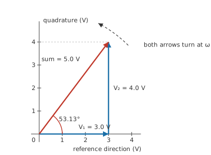
Freezing the picture is what makes the arithmetic possible. Two voltages of 3.0 V and 4.0 V, a quarter of a cycle apart, do not make 7.0 V when they sit in series. They make 5.0 V, since neither is at full size at the moment the other is. Drawn as two arrows at right angles, the answer is the diagonal, and the diagonal is what a meter across the pair reads.
Practitioner
Adding two voltages that never peak together
Working with phasors starts with a decision that has nothing to do with the circuit: which quantity is the reference. One phasor is drawn along the horizontal and given an angle of zero, and every other angle in the problem is measured from it. A series circuit usually takes the current, since the same current passes through every component; a parallel one takes the node voltage for the same reason. The choice is free and the final answers do not depend on it, but it has to be written down or the angles mean nothing.
After that the procedure is the one used for forces or velocities. Resolve each phasor into a piece along the reference direction and a piece at right angles to it. The piece at right angles is the quadrature component. Add all the reference pieces, add all the quadrature pieces, and the two totals are the sides of a right triangle whose hypotenuse is the answer:
The angle falls out of the same two totals: it is the arctangent of the quadrature total divided by the reference total, taken with a function that knows which quadrant the result belongs in. Complex numbers give the whole operation a compact notation, with the reference total as the real part and the quadrature total as the imaginary one.
Worked example — Two voltages a quarter cycle apart
Two sinusoidal voltages of the same frequency sit in series. The first measures 3.0 V and is taken as the reference, at 0°. The second measures 4.0 V and leads it by 90°.
One arrow lies along the reference direction and the other stands square to it, so each projects onto a single axis: the reference total is 3.0 V and the quadrature total is 4.0 V. Those two sides give a resultant of 5.0 V at 53.13° from the reference.
An AC voltmeter on each source reads only sizes, and their arithmetic total is 7.0 V. A third meter placed across the pair reads the phasor answer.
Right angles make the arithmetic look neater than it usually is, and nothing in the method needs them.
Worked example — The same two sizes, sixty degrees apart
The second source is moved to 60° ahead of the first, with both sizes unchanged.
Its contribution now splits between the two directions, and the totals become 5.0 V along the reference and 3.46 V in quadrature. The resultant is 6.08 V at 34.72°.
Bringing the two sources closer together in angle has made their sum larger and tilted it less. At zero separation the arrows point the same way and the total is the arithmetic one.
Kirchhoff's voltage law and current law survive the move to alternating current untouched, provided every sum in them is a phasor sum. Voltages round a loop still cancel and currents into a node still cancel. What changes is that a set of readings which would be nonsense on a DC bench, three volts and four volts making five, becomes the ordinary case. Two channels of an oscilloscope supply both halves of a phasor at once: the trace heights give the sizes and the horizontal offset between them gives the angle.
Engineer
One frequency at a time
Three numbers pin a sinusoid down completely: how big it is, how fast it repeats, and where in its cycle the clock finds it at the instant timing begins.
The middle one enters as the angular frequency, omega, which counts radians of the cycle covered per second:
In a linear circuit driven from a single source, omega is the same for every waveform in it. A resistor scales a sinusoid, a capacitor and an inductor differentiate and integrate it, and none of those operations alters its frequency, so the outputs come back as sinusoids of the same rate changed only in size and in starting angle. The term omega t is therefore carried by every quantity in the problem, and dragging an identical factor through every line of an algebra achieves nothing. Discard it, keep the pair of numbers that differs from one waveform to the next, and what is left is the phasor: an amplitude and an angle, or equivalently a single complex number.
The saving is larger than the bookkeeping suggests. Differentiating a sinusoid advances it by a quarter turn and multiplies its size by omega, and a quarter turn on the phasor plane is multiplication by j. Calculus over time collapses into multiplication by j times omega, a differential equation becomes an ordinary algebraic one, and the ratio of a voltage phasor to a current phasor becomes one number carrying both a size and an angle. That number is impedance, and it has no meaning outside the phasor picture.
No approximation has been made anywhere in that chain, so the phasor answer has to agree with the waveforms it came from.
Worked example — Checking the sum in the time domain
Give the pair of sources above a frequency of 400 Hz, so one cycle lasts 2.5 ms and the angular frequency is 2513 rad/s.
Sample both waves at 0.50 ms, a fifth of the way through a cycle, timed from the reference wave's upward zero crossing. The reference wave stands at 2.85 V and the leading one at 1.24 V, so the series pair supplies 4.09 V at that instant.
Take the phasor result instead, a single wave of size 5.0 V starting 53.13° ahead of the reference, and read it at the same instant: 4.09 V. The two routes agree, and they agree at every other instant as well.
The assumptions underneath the method are where a diagram can look correct and still describe nothing.
A phasor stands for a sinusoid at one stated rate, and a diagram is a snapshot of arrows all turning together. Put a second frequency on the same sheet and the arrows turn at different rates, so the picture is true for one instant and false immediately afterwards. Two such waves do not sum to a sinusoid at all; the shape they make repeats at the difference between their frequencies, and its peak really does reach the arithmetic total on the occasions when the two line up. A signal carrying harmonics has to be split into its components by a Fourier series, given one diagram per harmonic, and put back together in the time domain at the end.
Nothing here describes a circuit that has just been switched on. The expression above assumes a wave of constant size and constant frequency, running long enough for any starting transient to have decayed, so phasors are silent about the first few cycles after a supply is connected. That interval belongs to second-order transient analysis and, in general form, to transfer functions written in a variable that carries growth and oscillation in one expression.
The components have to be linear as well. Resistance, capacitance and inductance hand back the frequency they were given. A stage that clips or saturates manufactures frequencies that were never present at its input, and no arrow on the input diagram accounts for them.
One caution belongs with those but is not an assumption. A phasor is not a signal, and no instrument will ever display one. The arrow is a way of holding two facts about a waveform that remains, at every instant, an ordinary voltage on an ordinary wire.
Professional
The conventions that travel with a phasor
A phasor diagram carries no units and no record of the conventions that drew it, so both have to be stated alongside it.
Magnitude is the convention people trip over. Circuit theory usually gives a phasor the amplitude of the wave, matching the peak value in the expression above. Power engineering gives it the RMS value instead, since that is what meters read and what the power arithmetic expects:
Worked example — The same triangle in RMS volts
Scaling each source down to its RMS value gives 2.12 V and 2.83 V, and the resultant becomes 3.54 V.
Every length has shrunk by the same factor, so the triangle keeps its shape and the angle of 53.13° is unchanged. The convention decides what the numbers mean and leaves the geometry alone, so a diagram with unlabelled magnitudes can be read wrongly without ever looking wrong.
The reference waveform is the other convention worth pinning down. Some treatments define the phasor against a cosine and others against a sine, and the two differ by a quarter turn. An angle lifted out of one book and dropped into another's expression lands ninety degrees away from where it belongs. Within a single problem the choice makes no difference as long as it is used everywhere, and a diagram assembled from two sources is worth checking before any arithmetic starts.
Software solves circuits this way whether or not the phasor is mentioned. A small-signal AC sweep in a SPICE simulator computes a magnitude and an angle at every node for each frequency in turn, which is a phasor solution repeated across a sweep. That also explains why such a run reports nothing about clipping however large the drive is made. The same pair of numbers is what a vector network analyser measures directly, and what the two curves of a Bode plot present against frequency.
A phasor diagram is used more often as a check than as a calculation. In a series RC circuit the resistor voltage and the capacitor voltage are in quadrature, so their arithmetic total exceeds the source voltage while their phasor sum matches it; a reading that fails that test points at a measurement fault before it points at a broken component. AC circuit analysis turns the same habit into a routine. Where the angle between a voltage and a current has commercial weight, AC power and power factor take the argument further, and three-phase supplies are three phasors of equal length spaced a third of a turn apart, an arrangement that is far easier to reason about as a diagram than as three time expressions.
The limitation that catches working engineers is distortion. A single phasor for each line describes the fundamental and nothing else, so a supply feeding rectifier loads has harmonic current that appears nowhere on the diagram. A true-RMS meter counts that current and a phasor calculation based on the fundamental does not, and the two disagree by an amount that grows with the distortion. When they disagree the instrument is right and the diagram is incomplete.
Common mistakes
- Adding phasor magnitudes — sizes add arithmetically only when the arrows point the same way. Resolve into components first, or measure the diagonal.
- Putting two frequencies on one diagram — the arrows turn at different rates, so the picture holds for a single instant and is wrong by the next one. Each frequency needs a diagram of its own.
- Mixing peak and RMS magnitudes — a uniform scaling leaves the geometry intact, while a mixed one wrecks the answer and leaves the picture looking reasonable. Fix the convention before the first arrow goes down.
- Leaving the reference unnamed — every angle on the sheet is a difference, so without a stated zero the diagram cannot say which quantity leads.
- Carrying a phasor through a clipping stage — the output holds frequencies the input never had, and none of them belongs on the input's diagram.
- Expecting a phasor to describe switch-on — these are steady-state results, and the cycles immediately after power is applied are not steady state.
Frequently asked questions
What is a phasor?
It is a complex number standing in for a sinusoid of one fixed frequency. The magnitude is the size of the wave and the angle is where the wave sits in its cycle relative to a chosen reference. The time variation is left out, since every waveform in the circuit shares it.
Why don't two AC voltages add the way two DC voltages do?
Their peaks arrive at different moments, so neither source is contributing its full size when the other is. Only the components pointing the same way add directly. Two sources a quarter cycle apart contribute nothing at all to each other's direction, so their sum comes out as the diagonal of a rectangle instead of a straight total.
Is the length of a phasor the peak value or the RMS value?
Whichever the author chose. Circuit theory tends to use the peak, power engineering the RMS. The ratio between them is fixed for a sinusoid, so the shape of a diagram is the same either way and only the labels differ. Trouble starts when one diagram carries both.
Can phasors handle a square wave?
One harmonic at a time. The wave is first broken into sinusoids by a Fourier series, each of which gets its own phasor diagram at its own frequency, and the results are added back together as waveforms rather than as arrows.
Do phasors say anything about what happens at switch-on?
No. They describe the settled condition a circuit reaches after the transient has decayed. Predicting the first few cycles calls for the differential equation, or for a transfer function that carries both the decay and the oscillation.