
Quick Answer
A sine wave is the smooth, repeating voltage or current produced when something rotates at a steady rate. It is described by its peak value and its frequency, and it is the one repeating waveform a linear circuit can scale or delay without changing its shape. AC analysis is built on that property.
Intuition
A big wheel seen edge-on
A fairground big wheel turns at a steady rate. Seen from the side it is edge-on, so a passenger's sideways travel is invisible and only the change in height shows. That height climbs quickly past the bottom of the wheel, slows near the top, holds still for an instant, and comes back down. Drawn against time, the passenger's height is a sine wave.
The wheel never jerks, and the curve it traces has no corners and no straight sections. The steepest part is halfway up, level with the axle, where the passenger is moving vertically as fast as the wheel can carry anyone. The gentlest parts are the top and the bottom, where the motion is turning around.
An alternating voltage does the same thing in time. It starts at zero, rises to a maximum one way, comes back through zero, goes just as far the other way, and returns. One complete there-and-back is a cycle. The number of cycles in a second is the frequency, counted in hertz, and the largest value the voltage reaches is its peak.
Almost every generator feeding a grid is a machine that spins, so mains electricity arrives shaped like a passenger's height for the same reason. Bench instruments produce sine waves deliberately, because a single clean tone is the standard way to ask a circuit what it does. Direct and alternating current covers why supplies alternate at all; this lesson is about the shape they alternate in.
Practitioner
Putting numbers on the curve
A sine wave is fully described once its height, its repetition rate and its position in the cycle are known. The height is quoted as the peak value, the largest the waveform reaches in either direction. The repetition rate is the frequency f in hertz, and the time one whole cycle occupies is the period T:
Cycles suit a stopwatch and hinder the algebra, because the sine function wants an angle. One cycle is one full turn, and a full turn is 2π radians, so a wave at f hertz sweeps 2πf radians every second. That sweep rate is the angular frequency ω, in radians per second:
Worked example — A bench generator set to one kilohertz
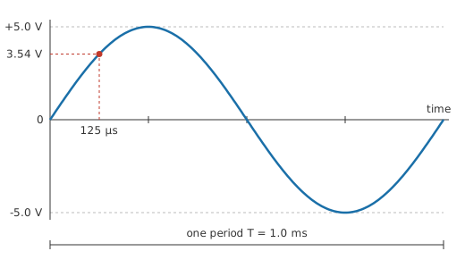
A signal generator is set to a sine of 5.0 V peak at 1.0 kHz.
One cycle then occupies 1.0 ms. The same setting written as an angular rate is 6283 rad/s, which is the form the instantaneous-voltage expression expects.
With the peak and the angular frequency fixed, the voltage at any instant is the sine of the angle reached so far:
The angle φ is the phase, and it sets where in the cycle the clock is started. On a single wave it is a free choice; between two waves of the same frequency it becomes the difference that matters, which phase and phase difference takes up. Timing from a wave's own upward zero crossing makes φ zero, and that is the convention used below.
Worked example — Reading the same wave at two instants
Time runs from the upward zero crossing, so the phase term drops out.
At 125 µs, an eighth of the way through the cycle, the wave stands at 3.54 V. At 250 µs, a quarter of the way through, it has reached the top of its swing: 5.0 V, the peak value itself.
One number is still missing, and it is the one a meter reports. The RMS value is the steady DC voltage that would heat a resistor at the same rate as the alternating one:
For the generator's wave that comes to 3.54 V. The square-root-of-two ratio belongs to the sine alone, so a peak figure and an RMS figure can never be swapped. Peak, peak-to-peak and instantaneous values sorts the conventions out and RMS value handles waveforms the ratio does not fit.
On the bench the division of labour is clean. An oscilloscope draws the shape and lets the period be read straight off the horizontal axis, while a multimeter on its AC range returns one RMS number and says nothing about shape. A function generator is set the other way round, by amplitude and frequency, and frequency and period builds the fluency needed to move between millihertz and gigahertz without losing a factor of a thousand.
Engineer
Why the shape comes out sinusoidal
A point on a circle of radius equal to the peak value turns at ω radians per second. Its height above the centre is the radius multiplied by the sine of the angle turned through, and after t seconds that angle is ωt. The projection of steady rotation onto one axis is the sine wave, which is the Layer 1 wheel written out as arithmetic:
An alternator makes this physical. A coil rotating in a uniform magnetic field links a flux that varies as the cosine of the rotation angle, and the voltage induced is proportional to how fast that flux is changing, which is a sine of the same angle. Steady rotation in, sinusoid out, with no design effort spent on the waveform.
Angle and time are two views of one quantity. The generator's wave has turned through 45.0° at the earlier of the two instants sampled above, which is why an eighth of a cycle and an eighth of a turn describe the same moment. Textbooks write the argument as ωt in radians and scopes measure it in seconds; converting between them needs nothing but the frequency.
The slope carries as much information as the height. A sine is steepest where it crosses zero and momentarily flat at each peak, so a wave's fastest rate of change is its peak value multiplied by ω. For the generator's wave that is 31.4 kV/s. Raise either the amplitude or the frequency and the demand on whatever has to follow that voltage rises with it. The consequence shows up immediately in capacitive reactance: a capacitor's current follows the rate of change of the voltage across it, so that current peaks at the zero crossings, a quarter cycle ahead of the voltage.
The wheel picture says nothing about why the sine gets special treatment in circuit theory, and the answer has more to do with the circuits than with the waveform. A circuit built only from resistance, capacitance and inductance of fixed value is linear and time-invariant. Such a circuit can multiply a sine by a constant and it can delay it, and there is nothing else it can do to it: no frequency comes out that did not go in. Every other repeating waveform is a sum of sines at multiples of the fundamental frequency, as harmonics and Fourier series set out. Since the circuit scales and delays each of those sines by a different amount, the mixture that emerges is no longer the mixture that went in, and the shape changes. A square wave fed through a filter comes out rounded; a sine comes out a sine. Single-tone testing rests on that survival, and so does the habit of describing a circuit by its response against frequency.
The instantaneous value an eighth of a cycle in and the RMS value of the same wave work out to the same figure, because the sine of 45 degrees and one over the square root of two are the same number. That coincidence is arithmetic and carries no meaning: RMS comes from averaging the square over a whole cycle, and no single instant defines it. The peak is an instantaneous value too, and it is what insulation and semiconductor ratings have to survive even though the RMS figure is the one usually quoted.
The expression describes a wave of constant amplitude and constant frequency that has been running forever, so it says nothing about a switch-on transient or about a signal whose amplitude is being modulated. Steady state is assumed. The word linear is doing heavy lifting too: a diode, a saturating magnetic core, a transistor driven past its limits or an amplifier hitting its rails will all take a pure sine and hand back something with new frequencies in it, and those extra frequencies are the definition of distortion.
Professional
How close a real signal gets
No source produces a perfect sine, and the gap is specified as total harmonic distortion: the harmonic content a source adds, as a fraction of the fundamental it is meant to be producing. A generator specified at 1.0 % of distortion, an illustrative figure and not a catalogue value, puts roughly 35 mV of unwanted content on top of the wanted wave. Whether that matters depends entirely on what is being measured. It is of no consequence in a filter's frequency response, and it sets the floor of the measurement when the thing under test is an amplifier's own distortion.
The harmonics land at exact multiples of the fundamental, which is what makes single-tone testing so useful diagnostically. One frequency goes in, and any other frequency that comes out was manufactured by the circuit. A spectrum showing the fundamental plus a descending row of multiples is a distortion measurement; a spectrum showing tones at unrelated frequencies is an intermodulation or a spurious-oscillation problem instead, and the two need different fixes.
How the sine is generated decides which of those it suffers from. An analog oscillator swings a resonant circuit or a feedback loop and produces a genuinely continuous waveform whose purity depends on how gently its amplitude is controlled. A direct digital synthesiser builds the wave from a stored table and a converter, so its frequency accuracy is as good as its clock and its purity is limited by the converter's resolution and by timing jitter. The characteristic result is spurs at frequencies unrelated to the output, which an analog oscillator does not produce. Frequency accuracy in either case comes from the timebase, usually quoted in parts per million and traceable to a crystal.
The amplitude control on a bench generator carries a trap that costs beginners an afternoon. Many instruments display the amplitude they would deliver into a 50 Ω load, because that is the convention their output stage is designed around. Connect that output to a high-impedance input, such as an oscilloscope's, and there is no load to halve the open-circuit voltage, so the real amplitude is twice the setting. The instrument is behaving as designed, and most have a menu setting for the load being driven. Reading the amplitude off the scope, not off the generator's display, sidesteps the question entirely.
Ratios between the various amplitude measures get used as specifications in their own right. The peak divided by the RMS value is the crest factor, and for a sine it is 1.41. True-RMS meters state the maximum crest factor they can handle before their reading degrades, and audio and power equipment is rated by how much headroom above the RMS level it can pass. A sine is the gentle case; pulsed and switched waveforms are far harsher on the same hardware.
Mains supplies deserve a caution of their own. Grid frequency is held very close to nominal, at 50 Hz across India and Europe and 60 Hz across North America, and the long-term average is regulated tightly enough that synchronous clocks keep time from it. The waveform is another matter. Rectifier-and-capacitor front ends throughout a building draw their current in short bursts at the tops of the cycles, and that current, pulled through the supply's own impedance, flattens the peaks. Equipment designed on the assumption of a textbook sine at the socket can behave differently once installed, and equipment measuring the supply has to be honest about what it is averaging.
For all of that, the sine keeps its place as the reference signal. A linear circuit's behaviour at every frequency, measured one tone at a time, describes it completely, which is what a Bode plot presents and what a swept measurement produces. The purity of the tone sets the floor of what such a measurement can resolve, so the quality of the source is part of the specification of the instrument.
Common mistakes
- Quoting a peak value where an RMS value is expected — a scope naturally shows peak and a meter naturally shows RMS, so one clean sine yields two different numbers and neither instrument is misreading. The convention has to travel with the number.
- Leaving the calculator in degree mode — the argument ωt comes out in radians. Degrees produce an answer that looks plausible and is wrong, which is worse than one that looks absurd.
- Assuming anything that repeats is a sine — square, triangular and pulsed signals repeat just as regularly and obey none of the sine relationships, starting with the RMS ratio. Check the shape before reaching for a formula.
- Mixing frequency and angular frequency in one expression — hertz counts cycles and radians per second counts angle. Substituting one for the other slips a factor of 2π into the result.
- Trusting a generator's amplitude display into a high-impedance input — many instruments calibrate that display for a 50 Ω load, so the delivered amplitude is twice what is shown. Measure it on the scope.
- Expecting a real oscillator to be spectrally clean — every source adds some harmonic content, and a distortion measurement can only resolve down to the purity of the tone driving it.
Frequently asked questions
What is a sine wave?
A voltage or current that varies smoothly and repeatedly, following the sine of an angle that advances steadily with time. It is the waveform a steadily rotating machine produces and the shape mains electricity is supplied in.
Why is mains electricity a sine wave rather than some other shape?
Generators rotate, and the voltage induced in a coil turning at a constant rate in a uniform magnetic field is sinusoidal without any effort being made to shape it. A sine also keeps its shape through transformers and long lines, which no other waveform manages.
What is the difference between frequency and angular frequency?
They measure the same repetition in different units. Frequency counts complete cycles per second in hertz; angular frequency counts radians of angle per second, and one cycle is 2π radians. Multiply frequency by 2π to get angular frequency.
Is every AC signal a sine wave?
No. Alternating simply means the polarity reverses, and square, triangular, pulsed and thoroughly irregular signals all qualify. The sine is the special case that circuit theory is built on, and other shapes are analysed as sums of sines.
Why do textbooks analyse circuits with single sine waves instead of real signals?
A linear circuit responds to a sine with a sine of the same frequency, changed only in size and timing, so one tone at a time gives a complete description. Real signals are then handled as combinations of tones the circuit has already been characterised for.