
Quick Answer
Three-phase power is an alternating supply of three voltages of equal size, each one third of a cycle apart. Connected in a star, the voltage between any two of the three lines is the square root of three times the voltage from a line to the neutral, and the three instantaneous powers add to a constant total.
Intuition
Three supplies, one shared return
A single alternating supply hands over its energy unevenly. Twice in every cycle the voltage passes through zero, and at those moments nothing at all is being delivered. A lamp or a kettle never notices, since a filament and a heating element are far too slow to follow the dip. A large motor is a different case, and feels every one of those gaps as a twitch in the shaft.
An engine with one cylinder has the same trouble. It fires once in a cycle and coasts through the rest of it, so the crankshaft speeds up and slows down within every turn. Give it three smaller cylinders instead and stagger their firing evenly around the cycle, and the same total power comes out smooth.
Three-phase supplies are built the same way. A generator carries three sets of windings spaced equally around it, so it produces three voltages of the same size, each one third of a cycle behind the one before. Whenever one of them is passing through zero the other two are between them carrying what the first cannot, and three matched loads fed from them receive a total that never dips.
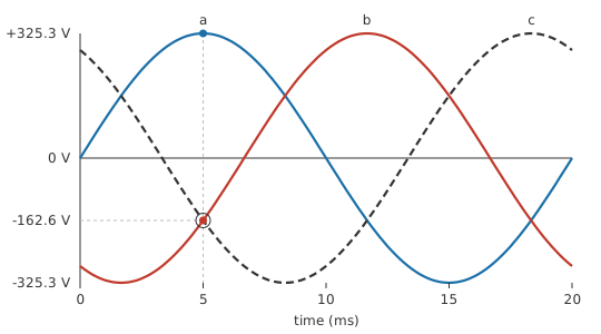
The three also share one return path. Run three separate single-phase circuits and six wires leave the supply; tie their far ends together and the returning currents cancel each other, so the same power reaches a workshop on four. In an Indian or European installation each line sits at 230 V to that shared point, and between any two lines there is 398.4 V. The larger of the two is the figure that catches people out.
Practitioner
Wye and delta, and which voltage is which
Three windings can be joined in either of two ways, and the choice applies equally to a generator, a transformer secondary and a load. A star connection, also called wye after the shape of the symbol, ties one end of each winding to a common point and takes the other three ends out as the lines. That common point is the neutral, and the supply earths it. A delta connection joins the windings end to end into a closed triangle and brings the lines off the corners, leaving no neutral.
Phase and line quantities then need keeping apart. Phase voltage and phase current belong to one winding, and line voltage and line current to the conductors going out to the installation. A star load's line current is its phase current, since one conductor carries both, while its line voltage is the larger figure. A delta swaps the pairing over.
The multiplier is the square root of three and not two, because the two phase voltages being compared are a third of a cycle apart instead of in opposition. Layer 3 does that subtraction.
Worked example — The supply and its two voltages
Each winding of the supply holds 230 V between its line and the neutral, at 50 Hz, so one cycle runs for 20 ms. Successive windings sit 120° apart in that cycle.
Between any two of the three lines the voltage comes to 398.4 V. Installations quote both figures together, phase first and line second.
Safety
The figure that earns this lesson a warning is the second one in that example: between any two lines of a 230 V supply there is 398.4 V, and anyone reaching into a three-phase board expecting the smaller number has already made the mistake that matters.
Switching off one phase does not make the board safe. The other two arrive on their own conductors and stay live, and a circuit fed from the phase you have opened can still be held at a dangerous voltage through a lamp, a contactor coil or a control transformer wired across to another phase. Prove every conductor dead, one at a time, with a tester you have proved on a known live source.
Rotation is a hazard in its own right: swap two lines and a motor turns backwards, which is how hoists and conveyors injure people during commissioning. Installation and maintenance work on three-phase supplies is regulated almost everywhere and belongs to a qualified electrician. The habits in electrical safety are a starting point and no substitute for that training, and every number on this page came off a calculator.
Worked example — A delta load and its line current
Every winding of a balanced delta load carries 10 A.
Two winding currents meet at each corner of the triangle, so the line leaving that corner carries 17.3 A instead.
Real power for a balanced load has one expression covering both connections, provided line quantities go into it.
Worked example — A balanced load on the same supply
The load draws 10 A in each line at a power factor of 0.85, and consumes 5.865 kW.
Read the same load one winding at a time and the answer has to agree. One winding takes 2.3 kVA and converts 1955 W of it, so three of them convert 5.865 kW.
Supplying that costs the cable and the protective device ahead of it 6.9 kVA.
The root three in that expression is the same factor arriving by another door: three times the per-phase product, rewritten in line quantities. Measuring any of it takes a clamp meter round each line and a voltmeter between pairs of lines, and a trustworthy real-power reading needs an instrument that multiplies the two waveforms together, as AC power sets out.
Engineer
Subtracting one phase from another
A line voltage is a difference. What appears between two lines is the potential of one phase minus the potential of the other at the same instant, and since the two are a third of a cycle out of step, the answer is neither their sum nor either one on its own.
Phasors turn that subtraction into arithmetic on components. Take the first phase as the reference direction, and the second lags it by a third of a cycle.
Worked example — The line voltage as a phasor difference
Phase a sits at 230 V along the reference direction, with nothing at right angles to it.
Phase b lags by 120°, which puts it at -115 V along the reference direction and -199.2 V across it.
Component by component, the first minus the second leaves 345 V and 199.2 V.
The magnitude of that difference is 398.4 V, agreeing with what the star relationship gave in Layer 2.
The geometry says the same thing without any components. Two phasors of equal length with a third of a cycle between them, drawn head to tail with one reversed, close an isosceles triangle whose apex angle is 120 degrees, so the closing side is twice the phase voltage times the sine of 60 degrees. Root three is that sine, doubled.
The three voltages written against time are one expression with three starting angles, and phasors are the shorthand for the set below.
Worked example — The three phases at one instant
Each phase peaks at 325.3 V, and at 50 Hz the angle advances at 314.16 rad/s.
Take the instant 5.0 ms after the reference phase crosses zero going positive, a quarter of the way through the cycle. Phase a is then at its peak, 325.3 V.
The other two are at -162.6 V and -162.6 V, both negative and both half the peak height.
Their total comes to 0.0 V, and it holds that value at every other instant as well.
A balanced star load returns nothing down its neutral for the same reason: three equal currents a third of a cycle apart cancel at the star point, so the fourth conductor can be there without carrying anything.
Power behaves the same way one level up. Each phase's own instantaneous power is its voltage times its current, and that product oscillates at twice the supply frequency, swinging above and below its average by the apparent power of that phase.
Worked example — One phase pulsates, three of them do not
At a power factor of 0.85 the current lags the voltage by 31.79°.
Taken alone, one phase of the balanced load peaks at 4255 W and dips to -345 W, handing power back to the supply during part of every cycle.
Add all three products at the start of the cycle and the total is 5865 W. Take it again at 1.7 ms, an instant picked for no reason at all, and the total is 5865 W.
A three-phase motor therefore receives a steady torque from a supply whose every individual conductor is pulsating, and a three-phase rectifier gets a supply that never falls to zero. Both results rest on conditions the algebra never stated.
Balance is the obvious one: three equal voltages, three equal loads, evenly spaced in the cycle. Disturb any of it and the neutral carries current, the star point drifts, and no single power factor describes the load any more. Behind that sits an assumption about frequency, since a third of a cycle is a phase angle and a phase angle means something only at one frequency. Each harmonic on a distorted waveform carries its own offset, and the third and its odd multiples land in step across all three phases instead of spread around the cycle.
The steady state is assumed as well. For the first cycles after a contactor closes, the currents carry a decaying component that belongs to no repeating cycle, so a cycle average describes nothing that is happening yet. And the constant total needs the currents to be sinusoids as much as the voltages are. A rectifier draws its current in short bursts near the peaks, and three such products still ripple.
Professional
Unbalance, rotation and third harmonics
An installation is never quite balanced. Single-phase circuits are spread across the three lines by whoever fills the distribution board, in the hope that the totals come out roughly equal, and the neutral carries whatever is left over.
Worked example — What the neutral carries when the load is uneven
Three single-phase loads on the three lines draw 12 A, 8.0 A and 5.0 A.
Resolved along the reference direction those three come to 5.5 A, and across it to -2.6 A.
The neutral therefore carries 6.08 A, well under the largest of the three loads and nowhere near their arithmetic total.
That result is the usual argument for a neutral no heavier than a line, and one class of load breaks it. A switched-mode power supply draws current in short bursts near the peaks of the waveform, rich in the third harmonic and its odd multiples. Those components complete three whole cycles while the fundamental completes one, so shifting a phase by a third of a fundamental cycle shifts them by a whole cycle: they arrive in step in all three phases and add in the neutral instead of cancelling there.
Worked example — Third harmonics arriving together
Each phase of a star-connected load carries 2.5 A at the third harmonic.
The neutral carries 7.5 A of it, three times the per-phase figure and independent of how well the fundamental is balanced.
An office floor full of electronic loads can run its neutral hotter than any of its lines. Current practice oversizes that conductor or runs one per phase, and the same currents circulate harmlessly around a delta winding upstream, which is one reason distribution transformers are wound with a delta somewhere in them.
The order in which the three phases reach their peaks is the phase sequence, or rotation, and it belongs to the supply as a whole, not to any one conductor. A motor turns whichever way its sequence tells it to, so two lines swapped at a terminal box reverse a pump or a machine tool. A sequence meter answers the question in seconds and is worth using after every reconnection. Motors and generators works through how the rotating field follows the sequence.
The two connections also become a design variable at starting. A motor wound for delta running takes the full line voltage across each winding; connect the same windings in star for the first few seconds and each sees only the phase voltage, so the current demanded from the line drops by a factor of 3.00, and the starting torque drops with it. Star-delta starters were the standard answer to inrush before electronic soft starters, and they are still fitted where the load can be brought up gently.
Ratings follow the line voltage. Clearances, insulation classes and the voltage printed on a contactor or a capacitor all refer to the largest voltage appearing between conductors it has to separate, so a part chosen against the phase figure is under-rated by root three. Motor run and start capacitors carry a rating picked against the connection they sit across, not against the supply's smaller number.
Correction works as it does on one phase, with three times the reactive power to supply and a bank of three capacitors wired in star or delta across the lines; power factor covers the sizing. What a distorted load may inject back into a shared supply is governed by a standard, and which standard applies depends on the market and the size of the installation.
One collision of names is worth clearing up before leaving the subject. The delta-wye transformation borrows both words for a piece of resistor-network algebra that has nothing to do with three-phase supplies; the shapes are the same, the problem is not. The supply-side chain, from a delta primary through a star secondary to the neutral a house is fed from, is followed in how electricity reaches your home.
Common mistakes
- Quoting the phase voltage where the line voltage belongs — the two differ by the square root of three, and a datasheet naming a system by both figures gives no clue which one a given specification means. Establish the connection before reading anything off.
- Multiplying line voltage by line current by three — the balanced-load expression takes the square root of three with line quantities. The plain factor of three goes with phase quantities.
- Sizing a neutral below the lines because the load is balanced — third-harmonic currents from electronic loads arrive in step and add there whatever the fundamental is doing.
- Reading a delta winding's current as the line current — each line carries the difference of two winding currents and is larger by root three. Clamp the line, not the winding, when a line figure is wanted.
- Treating a switched-off phase as dead — a lamp, a coil or a control transformer wired to another phase can hold it live through the load.
- Reconnecting a supply without checking rotation — two lines swapped reverse every motor on the board, and nothing else in the installation complains.
Frequently asked questions
Why is the line voltage 400 V when each phase is only 230 V?
The two phase voltages are a third of a cycle apart, so the difference between them is not twice either one. Doing the subtraction as phasors gives the square root of three times the phase voltage, which comes out close to 400 V for a 230 V phase.
What is the difference between star and delta?
Star ties one end of every winding to a shared point and brings the other ends out as lines, which makes a neutral available and puts the smaller voltage across each winding. Delta joins the windings into a closed triangle with the lines at the corners, offers no neutral, and puts the full line voltage across each winding.
Does the neutral carry current when the load is balanced?
Not at the fundamental frequency: three equal currents a third of a cycle apart cancel at the star point. Harmonics at the third and its odd multiples do not cancel, so a real neutral is rarely sitting at nothing.
Why three phases and not two, or six?
Smoothness alone does not settle it, since a two-phase quadrature pair also delivers a constant total. Three wins on conductors: the three returns cancel, so the fourth wire can be thin or absent, while a two-phase system needs a fourth wire or a shared return carrying more than either phase. Beyond three, the extra windings and conductors buy nothing further.
Can ordinary single-phase equipment run from a three-phase supply?
Yes. Each line taken with the neutral is an ordinary single-phase supply at the phase voltage, and a distribution board shares its circuits out across the three to keep the totals near equal. Equipment connected between two lines instead sees the line voltage and must be rated for it.
Knowledge check
A star-connected supply gives 240 V from each line to the neutral. What is the voltage between two lines? (Show answer)
A balanced delta load draws 6.0 A in each of its windings. What flows in each line? (Show answer)
A balanced load takes 20 A from each line of the same 398.4 V supply at a power factor of 0.90. What real power does it consume? (Show answer)
Each phase of a star-connected load carries 2.5 A of third-harmonic current. What appears in the neutral? (Show answer)
Three identical heaters are wired in star and the neutral conductor is then disconnected. What changes? (Show answer)
References
- IEC 60038, IEC standard voltages — the document that fixes 230 V line-to-neutral and 400 V line-to-line as the nominal values for 50 Hz low-voltage supplies. Consult the edition in force for the tolerance band around them.