
Quick Answer
An inductor saturates when its core can carry no more magnetic flux. Beyond that point extra current produces almost no extra flux, so the inductance collapses and the current rises far faster than the design expected. Saturation is a cliff rather than a gradual derating.
Intuition
Every domain already pointing the same way
A magnetic core is not empty. It is full of tiny regions, each of which is already magnetic and each of which is pointing in some direction. Left alone they point every which way and cancel out, which is why a lump of ferrite does not stick to the fridge.
Put current through a coil wound on that core and the regions start to line up with the field you are applying. Each one that swings into line adds its own magnetism to yours. This is the entire trick of a magnetic core: you supply a little field and the material supplies a lot more, which is why a few turns on ferrite do the job of a few hundred turns in air.
Now keep increasing the current. At some point every region is already pointing the way you want. There are no more left to recruit. From there on, extra current buys you only the field the current itself would have made in empty space — which, next to what the core was contributing, is almost nothing.
That is saturation, and the thing to notice is that it is not a gradual weakening. The core is helping, helping, helping, and then it has nothing more to give. The inductance goes with it.
An inductor that has saturated is not a weak inductor. It is a piece of wire.
Safety
A saturated inductor in a switching supply is a short circuit across the switch, and the switch is what dies. In the example worked through here the current reaches 1.08 A after 14 µs when the arithmetic promised 696 mA, and it is climbing without limit by 15.7 µs — the model has to be cut off at 1.8 A because nothing in an ideal coil stops it. What stops it in a real circuit is the winding resistance and the switch's own on-resistance, and the energy that would have gone into a magnetic field goes into the switch instead, in microseconds. This failure gives no warning and leaves no evidence except a destroyed semiconductor, which is why it is so often diagnosed as a bad transistor. Every number here is an invented illustration; the mechanism is not. Design against the saturation rating, not against the rms rating, and leave margin for the fact that the saturation rating falls when the part gets hot.
Practitioner
Where the inductance goes
Take one part and follow it: 12 turns on a ferrite ring of 40 square millimetres cross-section and a 60 mm magnetic path, at a relative permeability of 2000.
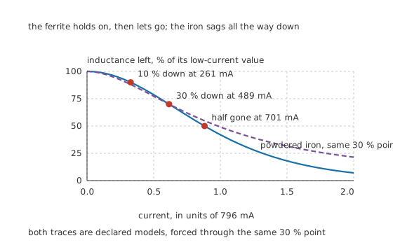
The ferrite holds on and then lets go; a powdered-iron core forced through the same 30 % point sags all the way down.
Worked example — The three currents everyone calls the saturation current
That winding gives 241 µH at low current. Against an illustrative ceiling of 400 mT, the current whose straight-line extrapolation would reach that ceiling is 796 mA.
The real curve turns over sooner. It is a tenth down at 261 mA, thirty per cent down at 489 mA — where the part is delivering 169 µH instead of its marked value — and half gone at 701 mA.
The first two of those are both used as datasheet ratings, and they differ by 1.88 times on the same piece of ferrite.
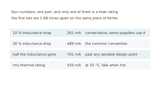
Only the last of the four is about heat.
The shape of that curve comes from a stated model, not from a measurement: flux density following a hyperbolic tangent of the applied field, which has the right slope at the origin and the right ceiling far from it. Real cores differ in the detail, particularly near the knee, and the numbers here are illustrations. The behaviour they illustrate is not.
Read the rating's own conditions before you use it. A saturation figure is quoted at a temperature, and often at a frequency and a DC bias too. The same part will be given a different number at 25 °C and at 100 °C, and a curve of inductance against bias current is far more use than any single figure taken off it. Where a supplier gives only one number and no condition, treat it as marketing rather than data.
The rms rating is a different measurement entirely. It is found by running current through the part until its temperature rises by some stated amount, typically twenty or forty degrees, and it says nothing about the core. A part can be well inside its rms rating and deep into saturation, or stone cold and perfectly linear while its winding quietly cooks. The two ratings constrain different failures and both have to be met.
Engineer
Why the current runs away instead of levelling off
The obvious mental picture of saturation is that the current stops responding — the core is full, so nothing more happens. That picture is backwards, and it is worth spending a moment on why.
The voltage across an inductor is the inductance multiplied by the rate of change of current. In a switching converter the voltage is set by the supply and does not care what the coil is doing, so it is the rate of change that has to accommodate. Halve the inductance and the current climbs twice as fast. Take the inductance away entirely and there is nothing left to limit it at all.
So saturation is a positive feedback loop. More current means less inductance means a faster climb means more current.
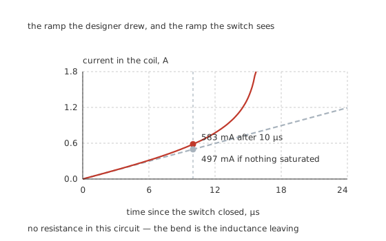
Neither trace bends because of resistance — there is none here. They bend because the inductance is leaving.
Worked example — What the extra microseconds cost
Hold 12 V across the coil and integrate the ramp with the inductance following the model rather than held constant.
After 6.0 µs the ideal answer is 298 mA and the real one 314 mA, a difference nobody would notice. After 10 µs it is 497 mA against 583 mA. After 14 µs it is 696 mA against 1.08 A, 1.55 times as much.
By 15.7 µs the integration has reached the 1.8 A ceiling it has to be cut off at, because an ideal coil with no inductance left has nothing to bound it.
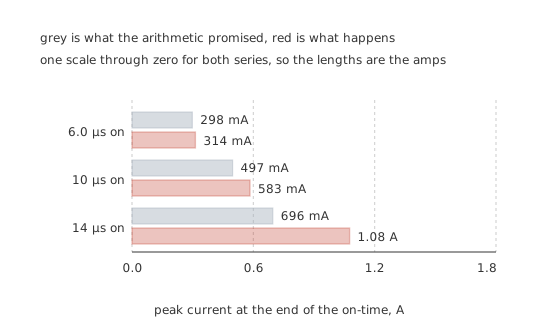
One scale through zero for both series, so the drawn lengths are the amps.
Look at the shape of that escalation. Going from 6.0 µs to 14 µs stretches the on-time by 2.33. The ideal current rises by exactly that factor, because a straight line is a straight line. The real current rises by 3.43, from 314 mA to 1.08 A. A control loop that widens a pulse by a third to hold its output can walk a converter into this without anything in the feedback path noticing.
The soft knee is worth having for exactly this reason. A powdered-iron core with its gap distributed through the material loses inductance gradually — it is already a few per cent down where ferrite is still at full value, and it still has something left where ferrite has none. That costs efficiency at the normal operating point and buys tolerance of an abnormal one. Which of the two you want is a real design decision.
Professional
The rating you were given is not the rating you have
Two things move the saturation current, and neither of them is on the front page of a datasheet.
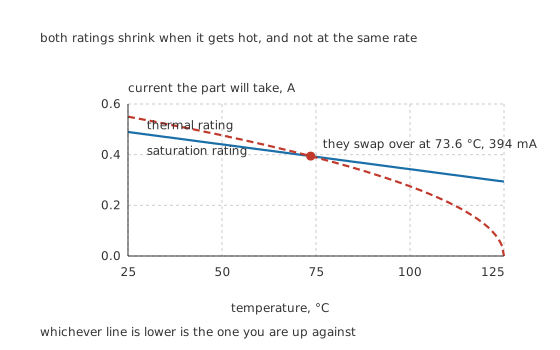
Whichever line is lower is the one you are up against.
Worked example — The same part, hot
A core's saturation flux density falls as it warms, here at an illustrative 0.40 %/°C.
From 489 mA at 25 °C, the saturation rating is down to 343 mA at 100 °C — a loss of 0.30 of what you started with, and the part has not been abused, only warmed.
The thermal rating moves the other way relative to it. Starting at 550 mA and falling to nothing at 125 °C, it drops faster, so the two cross at 73.6 °C and 394 mA. Below that temperature the core is your limit; above it the copper is.
That crossing is why a part chosen on the bench can fail in the product. Bench conditions are cool and the saturation rating is the binding one, so a design with a little margin against it looks safe. Inside a warm enclosure both ratings have moved, they have moved by different amounts, and the limit you are up against may no longer be the one you checked.
A gap changes the numbers and not the mechanism. Cutting an air gap into the magnetic path divides the effective permeability and multiplies the saturation current by the same factor, at the cost of needing more turns for the same inductance. That is the standard way to buy headroom, and the gap trade-off sets out its arithmetic. It does not make saturation gentler; it moves the cliff.
DC bias and ripple add. The saturation question is about the peak instantaneous current, so a converter carrying a steady 300 mA with 200 mA of ripple on top is asking the core about 400 mA, not 300. Datasheet curves are usually taken with a DC bias for exactly this reason, and reading one as though it applied to an rms value understates the peak.
Measuring it is easy and worth doing. Drive the part from a low-impedance source through a current-sense resistor, watch the current ramp on a scope, and look for the point where the straight ramp starts to curve upwards. The kink is the knee. An LCR meter will not find it, because it measures at a small signal with no DC bias — which is the condition under which every inductor looks fine.
Failures are diagnosed wrongly more often than not. The evidence of saturation is a destroyed switching device and an inductor that measures perfectly afterwards, because the core is undamaged. The part that looks guilty is the part that died, and the part that killed it tests good.
Where this arrives next
The same collapse in reverse is what a ferrite bead is built to exploit rather than avoid, and the DC bias in a common-mode choke is the case where two windings save each other from it.
Common mistakes
- Designing to the rms rating — the thermal rating here is 550 mA and the saturation rating is 489 mA at 25 °C. The lower of the two is the one that matters, and it is not the one printed largest.
- Comparing two suppliers' saturation currents — one may quote a 10 % inductance drop and the other 30 %. On this part those are 261 mA and 489 mA, a factor of 1.88, for identical silicon-free ferrite.
- Expecting the current to level off — it does the opposite. With 12 V held across the coil the real ramp reaches 1.08 A at 14 µs against an ideal 696 mA, and by 15.7 µs nothing in an ideal coil bounds it at all.
- Ignoring temperature — at 100 °C this core's saturation rating is 343 mA rather than 489 mA, a loss of 0.30 with no abuse involved.
- Using an rms figure for the saturation check — the core responds to the peak, so a steady current plus its ripple is what has to stay under the knee.
- Trusting an LCR meter to find the knee — it measures at small signal with no DC bias, which is the one condition in which a saturating part looks healthy.
Frequently asked questions
What does an inductor do when it saturates?
It stops being an inductor. The core has no more magnetic regions left to recruit, so extra current adds almost no flux, and with 12 V across it this example goes from 497 mA at 10 µs to 1.08 A at 14 µs and has no bound at all by 15.7 µs. What limits the current after that is the winding resistance and whatever is switching it.
Why do datasheets disagree about saturation current?
Because they are answering different questions. The current at a 10 % inductance drop is 261 mA here and the current at a 30 % drop is 489 mA — the same part, 1.88 times apart. Neither is wrong; you have to read which convention is being used before comparing two parts.
Does saturation damage the inductor?
Usually not. The core is unharmed and the part measures correctly afterwards, which is exactly what makes the failure hard to diagnose. The damage lands on the switching device that had to carry the runaway current.
How much does temperature move the saturation current?
On this illustration, 0.40 % per °C of saturation flux density, so the 489 mA rating at 25 °C becomes 343 mA at 100 °C. That is a loss of 0.30 of the rating from warmth alone, before any of the design's own margin is spent.
Is a soft saturation knee better?
It is more forgiving and less efficient. A powdered-iron core is already a few per cent down where ferrite is still at full value, and it still has inductance left where ferrite has none. If your control loop can occasionally overshoot, that tolerance is worth paying for.