
Quick Answer
Put a capacitor where the inverting amplifier's feedback resistor was and the output ramps at a rate set by the input, totalling it up. Put the capacitor at the input instead and the output reports how fast the input is changing. Neither circuit is usable exactly as drawn.
Intuition
The drift and the fall
Snow falls on a field and a drift builds against a wall. Two different quantities are in that sentence and people mix them up constantly.
How fast it is snowing is one thing: centimetres an hour, which you can measure by standing outside for a minute. How much has fallen is another: the depth of the drift, which is everything the last several hours delivered, added up. Neither tells you the other. A drift a metre deep says nothing about whether it is snowing now, and a heavy fall this minute says nothing about whether the ground was bare at breakfast.
The two op-amp circuits in this lesson are those two measurements.
One of them watches an input and adds it up: give it a steady voltage and its output climbs, at a rate the voltage sets, and where it gets to depends on how long you left it. The other one watches for change and reports only the rate: hold its input anywhere at all, steady, and its output is zero.
They are the same circuit with two components swapped over. And both of them, drawn as they appear in every textbook, will disappoint you the first time you build one.
Practitioner
Nowhere to go but into the capacitor
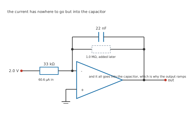
Four junction dots. The bleed resistor is drawn dashed because the circuit does not work without it.
Take the inverting amplifier and replace the feedback resistor with a capacitor. Everything else is unchanged: the summing node is still held at ground, the inputs still take nothing, and whatever current arrives through the input resistor still has exactly one place to go.
What has changed is what that place does with it. A resistor turns a current into a voltage immediately. A capacitor turns a current into a voltage that keeps growing for as long as the current flows.
Worked example — Where it gets to, and how fast
An invented network: 33 kΩ in, 22 nF back. Apply 2.0 V and the input resistor delivers 60.6 µA to the summing node.
Over 200 µs that current delivers 12.1 nC of charge into the capacitor, which puts the output at -551 mV.
The rate is the input divided by 726 µs, which is 2755 V/s. It does not change with time, so the output reaches the 13.5 V rail at 4.90 ms.
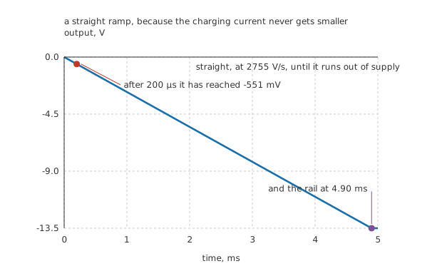
Straight, not curved. Nothing here is an exponential.
The ramp is straight, and that is the whole point of using an amplifier for this. An RC network on its own approximates integration only while its output stays small, because the growing voltage across the capacitor reduces the current charging it and the curve bends away. Here the summing node does not move, so the charging current never falls off, and the output is a straight line all the way to the rail.
That live lesson owns the curve and the conditions under which the approximation holds. This one owns the line, and it is a line because of the virtual ground and for no other reason.
Engineer
The circuit as drawn does not work
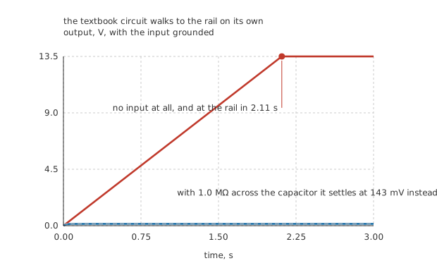
Both traces start together at zero. Only one of them stays anywhere useful.
Ground the input. There is now no signal, no current through the input resistor, and no reason for the output to move.
It moves anyway.
Worked example — What it integrates when there is nothing to integrate
Give the amplifier an invented input offset voltage of 2.0 mV. That looks exactly like a real input, so the circuit ramps at 2.75 V/s.
Give it an invented input bias current of 80 nA. That current also has nowhere to go but the capacitor, adding 3.64 V/s.
Together they give 6.39 V/s, and the output is against the rail in 2.11 s.
An integrator is the one circuit where offset and bias current stop being small print. Everywhere else they add a fixed error you can measure and ignore; here they are integrated too, so the error grows without limit until the amplifier runs out of supply. Two millivolts, which nobody would think about in an amplifier, empties the useful range of this one in a couple of seconds.
Worked example — The bleed resistor, and what it costs
Put 1.0 MΩ across the capacitor. Now the offset and bias have somewhere to go other than the capacitor, and the output settles at 143 mV instead of climbing.
The price is that the circuit stops integrating below 7.23 Hz, where the resistor's path is easier than the capacitor's. Its gain at DC is now just 30.3, and the circuit is a low-pass filter rather than an integrator down there.
Which is the whole trade: it integrates above that corner and it does not drift, and you cannot have both.
Real integrators go further. A switch across the capacitor resets the output to zero on demand, which is how an integrating converter works and why the circuit is used in measurement at all: it integrates for a known interval, is read, and is reset. Nothing is asked to hold a total for hours.
Professional
Swap the two components over
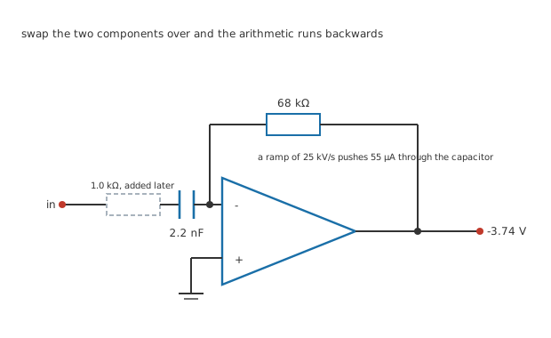
Two junction dots. The series resistor is dashed for the same reason the bleed resistor was.
Put the capacitor at the input and the resistor in the feedback path and every step of the argument runs backwards. A capacitor passes current only when the voltage across it is changing, and the summing node holds one of its plates still, so the current through it is set entirely by how fast the input is moving.
Worked example — Reporting the slope
An invented network: 2.2 nF in, 68 kΩ back. Feed it a ramp of 5.0 V over 200 µs, which is 25 kV/s.
The capacitor passes 55 µA, and all of it goes through the feedback resistor.
The output sits at -3.74 V and stays there for as long as the ramp continues, however far the input has got to.
The two components give a time constant of 150 µs, and that number will matter again in a moment for a reason that has nothing to do with ramps.
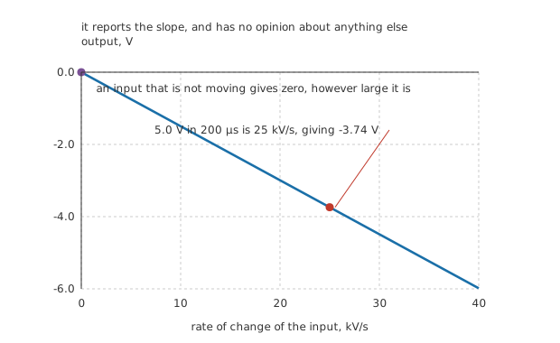
Through the origin. A stationary input gives zero however large it is.
And this one has a worse problem
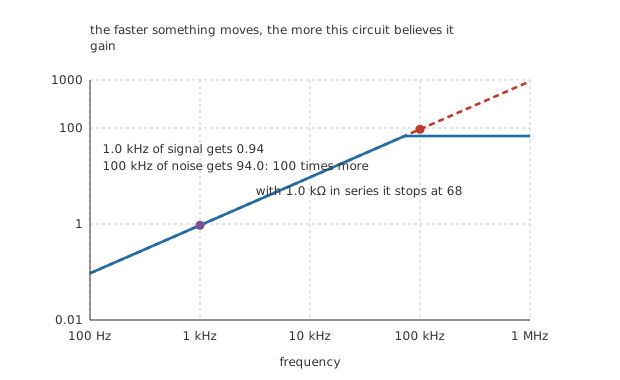
Same line until the limit binds. The dashed trace keeps going.
The differentiator's gain rises in proportion to frequency, and that is not a side effect but the definition of what it does. The trouble is that noise has high-frequency content and signals usually do not.
Worked example — What it does to the noise
The gain reaches one at 1064 Hz, so a 1.0 kHz signal gets 0.94.
A 100 kHz noise component, well above anything you care about, gets 94.0.
That is 100 times more gain for the noise than for the signal, and the amplifier has no way of telling them apart.
The fix is the same shape as the integrator's. Put 1.0 kΩ in series with the capacitor and the gain can no longer exceed 68, which it reaches at 72.3 kHz. Below that the circuit differentiates as before; above it, it is an inverting amplifier with a fixed gain and the noise stops winning.
A bare differentiator is also a stability problem, for a reason that belongs to the next-but-three lesson. Rising gain with frequency is exactly what a feedback loop cannot tolerate, and a differentiator with no series resistor will often oscillate rather than merely amplify noise. Real op-amp limitations works through why.
Which to reach for
Use an integrator when you want a total, and design the reset before you design anything else.
Use a differentiator when you want an edge, and expect to fight the noise. Where the job is really edge detection rather than differentiation, a comparator is usually the better instrument.
Both circuits need their extra component. The bleed resistor and the series resistor are not refinements. They are the difference between a circuit and a diagram.
And both are still inverting amplifiers. Everything the previous lessons said about the summing node, the source resistance and the output current applies unchanged.
Common mistakes
- Expecting an exponential from the active integrator — the output is a straight line at 2755 V/s, because the summing node does not move and the 60.6 µA charging current never falls off. The curved version belongs to the passive RC circuit, and the difference is the whole reason to use an amplifier.
- Building an integrator without a bleed resistor — 2.0 mV of offset and 80 nA of bias give 6.39 V/s of drift with the input grounded, and the output is against the rail in 2.11 s. The circuit as drawn in textbooks is a diagram, not a design.
- Forgetting what the bleed resistor costs — 1.0 MΩ across 22 nF stops the circuit integrating below 7.23 Hz and caps its DC gain at 30.3. That is the trade, and there is no way round it other than a reset switch.
- Building a differentiator without a series resistor — its gain reaches 94.0 at 100 kHz against 0.94 at 1.0 kHz, so noise gets 100 times the signal's gain. 1.0 kΩ in series caps it at 68 from 72.3 kHz upwards.
- Reading a differentiator's output as a measure of the input — it reports the slope. A steady 10 V and a steady 0 V give the same answer, which is zero, and that is the circuit working correctly.
- Assuming an integrator can hold a total indefinitely — even with the bleed resistor it settles at 143 mV of its own accord. Anything that needs a long total needs a reset and a known interval.
Frequently asked questions
Why is the active integrator's ramp straight when an RC's is curved?
Because the summing node is held at ground. In a plain RC the voltage across the capacitor is also the voltage that reduces the charging current, so the current falls as the output rises and the curve bends. Here the capacitor's left plate stays at zero however far the output goes, so the input resistor sees a constant voltage and delivers a constant 60.6 µA.
Does the bleed resistor stop it being an integrator?
Below the corner, yes. At 7.23 Hz the resistor's path becomes easier than the capacitor's, and below that the circuit is an inverting amplifier with a gain of 30.3. Above it the capacitor dominates and the circuit integrates normally. The design question is whether the frequencies you care about are all above the corner.
Why does bias current matter more here than in other circuits?
Because it is integrated. In a resistive amplifier a bias current produces a fixed error voltage across whatever resistance it flows through, and you either tolerate it or cancel it. Here it flows into the capacitor and its effect grows with time: 80 nA into 22 nF is 3.64 V per second, and nothing stops it.
Can I use a differentiator to get a clean edge from a slow signal?
You can get an edge and it will not be clean, because everything faster than your signal is amplified harder than your signal is. A differentiator with a series resistor helps, and a comparator with hysteresis usually helps more, because it makes a decision rather than reporting a rate.
What sets how long an integrator can run before it saturates?
The rate and the rail. At 2755 V/s from a 2.0 V input the output covers 13.5 V in 4.90 ms, so that is the longest useful interval at that input. Halve the input or double the RC product and it doubles. Design the interval first and the components second.