
Quick Answer
An input resistor and a feedback resistor meet at the op-amp's inverting input, and the amplifier holds that node at ground without connecting it there. Whatever current arrives through the input resistor leaves through the feedback resistor, so the gain is minus the ratio of the two.
Intuition
A plank across a fixed pivot
Put a plank across a pivot and stand on one end. The other end goes up, by an amount set only by where the pivot sits: a short arm on your side and a long one on the other multiplies your movement, and the pivot itself does not move at all.
The inverting amplifier is exactly that arrangement, and the pivot is the interesting part.
There is a node in the circuit where the input resistor meets the feedback resistor, and the op-amp works to hold that node at zero volts. Not by connecting it to ground: nothing connects it to ground. It holds it there by moving its output to whatever voltage makes the currents balance, which is the second golden rule doing its job. The node is at ground potential and is not grounded, and the name for that is a virtual ground.
Once you accept the pivot does not move, the rest is arithmetic you can do in your head. A voltage on the input side pushes a current through the input resistor towards a node that is at zero volts. That current has nowhere to go except the feedback resistor, because the amplifier's inputs take none of it. And a current flowing out through the feedback resistor from a node at zero volts means the far end of that resistor is below zero.
Push in, and the output goes down. That is where the name comes from, and it is the one genuinely awkward thing about the circuit.
Practitioner
In one resistor and out the other
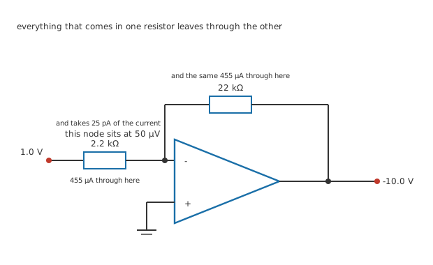
Two junction dots, at the summing node and where the feedback resistor taps the output. Every other meeting is a corner.
The circuit is the batch's invented amplifier — an open-loop gain of 200000, 2.0 MΩ between the inputs, an output reaching 13.5 V and supplying 25 mA — with 2.2 kΩ from the source to the inverting input and 22 kΩ from there back to the output. The non-inverting input goes to ground. Every one of those figures is invented for this lesson and belongs to no real part or real design.
Worked example — Following the current round
Put 1.0 V on the input. The summing node is at ground, so the whole of that appears across 2.2 kΩ and drives 455 µA towards the node.
The amplifier's inputs take 25 pA of it, which is 0.0000055 % of what arrived. Everything else continues through 22 kΩ.
That current leaving a node at zero volts puts the far end at -10.0 V, so the gain is -10.0.
Nothing in that calculation used the op-amp's gain. It used the assumption that the summing node sits at zero and takes no current, which is the two golden rules, and it produced an answer that depends only on two resistors.
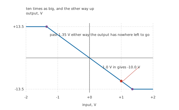
Straight through the origin with no offset, and flat once the output runs out of rail.
The line goes through the origin because nothing in the circuit adds anything. It stops being a line at 1.35 V in either direction, where the output reaches 13.5 V and has nowhere left to go. Past that point the amplifier is doing its best and the answer is wrong, which is what clipping is.
Worked example — How good the two rules are here
The fraction of the output fed back is 0.0909, so the loop gain is 18182.
The rules are therefore out by 0.0055 %, which is one divided by one plus that.
Against resistors you can buy to a tenth of a per cent, the amplifier is contributing nothing worth measuring.
Engineer
Why "virtual" is the right adjective
The summing node is not at zero volts. It cannot be, because the amplifier only produces an output when there is a difference at its inputs, and the non-inverting input really is at zero.
Worked example — Where the pivot actually sits
The output is at -10.0 V. Divide by the open-loop gain of 200000 and the summing node must be at 50 µV.
Across the amplifier's 2.0 MΩ that draws 25 pA.
Against the 455 µA arriving through the input resistor, that is 0.0000055 %, which no instrument in an ordinary workshop can find.
So the node is at ground as far as any measurement goes, and it is not grounded, and both halves of that matter. It behaves like ground for the signal: a second resistor connected to it would carry current set only by its own voltage and its own value, which is what makes summing amplifiers work. And it is not ground for the circuit: cut the feedback resistor and the node stops being anywhere near zero, because nothing was holding it.
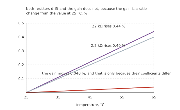
All three start at zero at 25 °C, so the vertical axis is genuinely zero-based.
The gain is a ratio, and that is worth more than it sounds
Both resistors are in the same package, on the same board, at the same temperature, and the gain is their ratio. Anything that happens to both of them cancels.
Worked example — What warming the board does
Give the input resistor an invented temperature coefficient of 0.010 %/°C and the feedback resistor one that differs from it by 0.0010 %/°C.
Warm the board by 40 °C. The input resistor rises 0.40 % and the feedback resistor rises 0.44 %.
The gain moves 0.040 %, which is the mismatch and nothing else. Almost the whole of both drifts cancelled.
This is the argument from the integrated circuit lesson appearing in a discrete circuit. Two resistors from the same reel, mounted side by side, track each other far better than either tracks its own nominal value, and a gain built from their ratio inherits the good behaviour rather than the bad.
Professional
The catch, and it is a real one
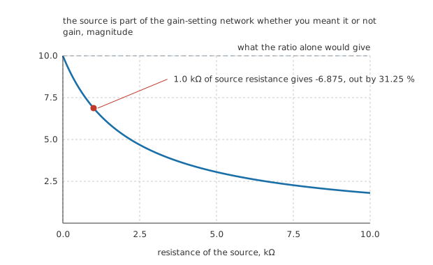
The dashed rule is what the ratio alone would give. The curve leaves it immediately.
Here is what catches people. The input resistance of this circuit is 2.2 kΩ, and that is not a coincidence or an approximation: the summing node is held still, so the source is driving 2.2 kΩ into what is effectively ground.
Which means any resistance in the source adds to it.
Worked example — What a middling source does to the gain
Drive the circuit from a source with 1.0 kΩ of its own resistance. The gain-setting network is now 1.0 kΩ plus 2.2 kΩ, whether you drew it that way or not.
The gain falls from -10.0 to -6.875.
That is an error of 31.25 %, from a source resistance many designers would not think to write down.
The error is not a rounding problem or a second-order effect. It is a third of the answer, and it appears with no symptom other than the gain being wrong.
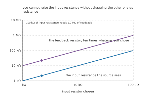
Same line, one decade apart, everywhere. That decade is the gain.
The obvious fix is to make the input resistor much larger than any source you will meet, and the figure above is why that is not free. Holding the gain at -10.0 means the feedback resistor is always ten times the input resistor, so raising one raises the other. Ask for 100 kΩ of input resistance and you need 1.0 MΩ of feedback, and very large resistors bring their own problems: they turn the amplifier's input current into a real error voltage, they pick up interference, and stray capacitance across them starts to matter at frequencies you cared about.
The honest answer is that this topology has a low input resistance and no way round it. The non-inverting amplifier has the opposite property, and that is most of the reason it is the next lesson.
What the output has to supply
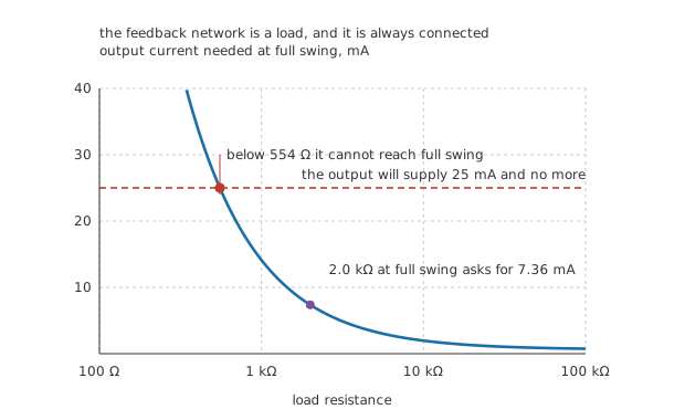
The curve does not reach zero on the right, because the feedback resistor is always connected.
Worked example — Everything the output is driving
Into 2.0 kΩ at -10.0 V, the load takes 5.0 mA.
The feedback resistor takes 455 µA on top of that, so the output supplies 5.45 mA altogether, which is 4.6 times inside its 25 mA limit.
At full swing into a smaller load the sum reaches the limit at 554 Ω, and below that the circuit clips early for a reason that has nothing to do with the rails.
Reading one on a schematic
Find the feedback resistor first. It runs from the output to the inverting input, and its far end tells you which topology you are looking at.
Then find where the input resistor lands. On the inverting input, this is an inverting amplifier and the gain is minus their ratio.
Check what the non-inverting input is tied to. Ground here. On a single supply it will be at mid-rail instead, and everything shifts up with it.
Look at the source. If it has any resistance of its own, add it to the input resistor before believing the gain. 1.0 kΩ on a 2.2 kΩ input is 31.25 % of error.
Common mistakes
- Reading the input resistance off the wrong resistor — it is the input resistor, 2.2 kΩ here, and nothing else. Not the feedback resistor, not the op-amp's own 2.0 MΩ, and not something large because op-amps have high input impedance.
- Ignoring the source resistance — 1.0 kΩ in front of a 2.2 kΩ input resistor turns a gain of -10.0 into -6.875, an error of 31.25 %. Nothing else in the circuit changed and nothing looks wrong.
- Treating the summing node as grounded — it sits at 50 µV and is held there by the feedback. Break the feedback and it stops being anywhere near zero, which is why an inverting amplifier with a lifted feedback resistor slams to a rail rather than passing signal.
- Raising the input resistor without thinking about the other one — holding the gain at 10.0 means 100 kΩ of input resistance forces 1.0 MΩ of feedback, and large feedback resistors bring input-current errors, pickup and stray capacitance with them.
- Forgetting the feedback resistor loads the output — at full swing the 22 kΩ takes 0.61 mA before any load is connected, and the 25 mA limit arrives at 554 Ω rather than at the load resistance you would compute alone.
- Expecting the gain to be as good as the resistors are accurate — it is as good as the resistors match, which is much better. A 0.40 % drift in both moved the gain 0.040 %, because only the 0.44 % against 0.40 % mismatch survives.
Frequently asked questions
Why is the non-inverting input grounded rather than left open?
Because it is the reference the amplifier compares against, and an open input has no defined voltage. Grounding it is what makes the summing node settle at zero. On a single supply it goes to a mid-rail reference instead, and the whole circuit then works about that point rather than about zero.
What sets the input resistance if the amplifier's own input is megohms?
The input resistor, because the far end of it is held at a fixed voltage. A source connected to it sees 2.2 kΩ to what is effectively ground, and the amplifier's 2.0 MΩ never enters the calculation. This is the topology's defining weakness and it is not fixable within the topology.
Does the gain really not depend on the op-amp at all?
Not measurably. The loop gain here is 18182, so the golden rules are out by 0.0055 %, which is far below the tolerance of any resistor you would buy. It stops being true when the loop gain is small, which happens when the circuit's gain is large, when the amplifier is poor, or at frequency.
Can I put a resistor in series with the non-inverting input?
Yes, and there is a reason to: matching it to the parallel combination of the two gain resistors makes the amplifier's input bias currents produce equal errors at both inputs, which then cancel. It does nothing for the gain and nothing for the input resistance, and it matters only when the bias currents are large enough to notice.
Why does an inverting amplifier need a smaller signal than a non-inverting one to clip?
It does not, in itself. Clipping happens when the output reaches 13.5 V, and here that takes 1.35 V in because the gain is 10. Any circuit with the same gain clips at the same input. What differs between the topologies is that a non-inverting amplifier's gain can never be less than one, so it cannot be used to attenuate.